Fluid Mechanics & Thermodynamics Engineering Fundamentals
Explore core mechanical engineering concepts including fluid properties, Pascal's law, Bernoulli's equation, and the laws of thermodynamics with examples.
MET001 — Basic Mechanical Engineering
Fluid Mechanics and<br>Thermodynamics Fundamentals
Basic Mechanical Engineering | MET001
Presented By:
<span style="opacity: 0.7;">Roll No. 38</span> — Diya<br><span style="opacity: 0.7;">Roll No. 39</span> — Geeta<br><span style="opacity: 0.7;">Roll No. 40</span> — Harshit<br><span style="opacity: 0.7;">Roll No. 42</span> — Ishaan
<span style="opacity: 0.7;">Roll No. 43</span> — Ishant<br><span style="opacity: 0.7;">Roll No. 44</span> — Jatin<br><span style="opacity: 0.7;">Roll No. 45</span> — Kamal
First Year Mechanical Engineering | 2025–26
02
Fluid Properties
Presented by: Diya (Roll No. 38)
Mass per unit volume <span style="margin: 0 10px; color:#F39C12; opacity:0.5;">|</span> <span style="color:#F39C12; font-weight:600">ρ = m/V</span> <span style="margin: 0 10px; color:#F39C12; opacity:0.5;">|</span> Units: kg/m³
Ratio of fluid density to water density <span style="margin: 0 10px; color:#F39C12; opacity:0.5;">|</span> <span style="color:#F39C12; font-weight:600">SG = ρ_fluid / ρ_water</span> <span style="margin: 0 10px; color:#F39C12; opacity:0.5;">|</span> Dimensionless
Resistance to flow/deformation <span style="margin: 0 10px; color:#F39C12; opacity:0.5;">|</span> <span style="color:#F39C12; font-weight:600">Dynamic & Kinematic</span> <span style="margin: 0 10px; color:#F39C12; opacity:0.5;">|</span> Units: Pa·s, m²/s
Cohesive force at liquid surface <span style="margin: 0 10px; color:#F39C12; opacity:0.5;">|</span> <span style="color:#F39C12; font-weight:600">Causes capillary action</span> <span style="margin: 0 10px; color:#F39C12; opacity:0.5;">|</span> Units: N/m
MET001 | Fluid Mechanics and Thermodynamics Fundamentals | First Year Mechanical Engineering
03
Types of Fluids
Presented by: Geeta (Roll No. 39)
IDEAL FLUID
No viscosity, incompressible, no shear stress
Theoretical model
REAL FLUID
Has viscosity and compressibility, follows Newton's law
Water, Oil
NEWTONIAN FLUID
Viscosity constant regardless of shear rate | τ = μ(du/dy)
Water, Air
NON-NEWTONIAN FLUID
Viscosity changes with shear rate
Blood, Paint, Toothpaste
COMPRESSIBLE FLUID
Density changes with pressure | ρ ≠ constant
Gases
INCOMPRESSIBLE FLUID
Density constant with pressure | ρ = constant
Liquids
MET001 | Fluid Mechanics and Thermodynamics Fundamentals
04
Newton's Law of Viscosity
Presented by: Geeta (Roll No. 39)
Definition
The shear stress between adjacent fluid layers is proportional to the velocity gradient (rate of shear strain) between them.
τ = μ (du/dy)
τ
= Shear Stress (Pa)
μ
= Dynamic Viscosity (Pa·s)
du/dy
= Velocity Gradient (s⁻¹)
ENGINEERING SIGNIFICANCE
Basis for viscosity measurement
Applied in pipe flow design
Used in lubrication engineering
Foundation for Navier-Stokes equations
Fixed plate (velocity = 0)
Moving plate (velocity = U)
y = distance from fixed plate
u = fluid velocity at y
U
τ = shear stress
du/dy = velocity gradient
h
MET001 | Fluid Mechanics and Thermodynamics Fundamentals
05
Pascal's Law
Presented by: Harshit (Roll No. 40)
Pressure applied to an enclosed fluid is transmitted equally and undiminished in all directions throughout the fluid.
P = F / A
P = Pressure (Pa) • F = Applied Force (N) • A = Cross-sectional Area (m²)
F₁ / A₁ = F₂ / A₂
Applications
<div style="flex:1; background: rgba(0,0,0,0.2); border: 1px solid rgba(255,255,255,0.1); padding: 25px; border-radius: 8px; text-align: center; box-shadow: 0 4px 15px rgba(0,0,0,0.1); display: flex; flex-direction: column; align-items: center justify-content: center;"> <svg viewBox="0 0 24 24" width="56" height="56" fill="#F39C12"> <path d="M12 2C6.48 2 2 6.48 2 12s4.48 10 10 10 10-4.48 10-10S17.52 2 12 2zm0 18c-4.41 0-8-3.59-8-8s3.59-8 8-8 8 3.59 8 8-3.59 8-8 8zm-1-13h2v4h-2zm0 6h2v2h-2z"/> </svg> <div style="margin-top: 15px; font-size: 22px; font-weight: 700; color: white;">Hydraulic Brake</div> </div>
<div style="flex:1; background: rgba(0,0,0,0.2); border: 1px solid rgba(255,255,255,0.1); padding: 25px; border-radius: 8px; text-align: center; box-shadow: 0 4px 15px rgba(0,0,0,0.1); display: flex; flex-direction: column; align-items: center justify-content: center;"> <svg viewBox="0 0 24 24" width="56" height="56" fill="#F39C12"> <path d="M5 21h14v-2H5v2zm7-11.5c-2.33 0-5 1.17-5 3.5V17h10v-4c0-2.33-2.67-3.5-5-3.5zm-5-3h10v2H7v-2z"/> </svg> <div style="margin-top: 15px; font-size: 22px; font-weight: 700; color: white;">Hydraulic Lift</div> </div>
<svg viewBox="0 0 1000 800" style="width: 100%; height: auto; max-height: 800px; font-family: 'Helvetica Neue', Helvetica, Arial, sans-serif;"> <defs> <pattern id="smallGrid" width="20" height="20" patternUnits="userSpaceOnUse"> <path d="M 20 0 L 0 0 0 20" fill="none" stroke="rgba(255,255,255,0.02)" stroke-width="1"/> </pattern> <pattern id="grid" width="100" height="100" patternUnits="userSpaceOnUse"> <rect width="100" height="100" fill="url(#smallGrid)"/> <path d="M 100 0 L 0 0 0 100" fill="none" stroke="rgba(255,255,255,0.06)" stroke-width="2"/> </pattern> <pattern id="diagHatch" width="12" height="12" patternTransform="rotate(45 0 0)" patternUnits="userSpaceOnUse"> <line x1="0" y1="0" x2="0" y2="12" stroke="rgba(255,255,255,0.15)" stroke-width="2" /> </pattern> <marker id="arrowFDir" viewBox="0 0 10 10" refX="6" refY="5" markerWidth="6" markerHeight="6" orient="auto"> <path d="M 0 1 L 9 5 L 0 9 z" fill="#F39C12" /> </marker> <marker id="arrowFDirWhite" viewBox="0 0 10 10" refX="6" refY="5" markerWidth="6" markerHeight="6" orient="auto"> <path d="M 0 1 L 9 5 L 0 9 z" fill="#FFFFFF" /> </marker> <marker id="arrowFDirWhiteLeft" viewBox="0 0 10 10" refX="6" refY="5" markerWidth="6" markerHeight="6" orient="auto-start-reverse"> <path d="M 0 1 L 9 5 L 0 9 z" fill="#FFFFFF" /> </marker> <marker id="arrowF" viewBox="0 0 10 10" refX="5" refY="5" markerWidth="5" markerHeight="5" orient="auto"> <path d="M 0 2 L 8 5 L 0 8 z" fill="rgba(255,255,255,0.6)" /> </marker> </defs> <rect width="1000" height="800" fill="url(#grid)" rx="8" /> <!-- Fluid Volumes --> <path d="M 254,350 L 254,696 L 946,696 L 946,350 L 554,350 L 554,554 L 346,554 L 346,350 Z" fill="rgba(52, 152, 219, 0.25)" /> <path d="M 254,350 L 254,696 L 946,696 L 946,350 L 554,350 L 554,554 L 346,554 L 346,350 Z" fill="url(#diagHatch)" /> <!-- Fluid Flow Transmission Lines Inside Pipe --> <g stroke="rgba(255,255,255,0.4)" stroke-width="4" marker-end="url(#arrowF)"> <line x1="275" y1="430" x2="275" y2="500" /> <line x1="325" y1="450" x2="325" y2="520" /> <line x1="400" y1="590" x2="480" y2="590" /> <line x1="450" y1="630" x2="530" y2="630" /> <line x1="650" y1="600" x2="730" y2="600" /> <line x1="700" y1="650" x2="780" y2="650" /> <line x1="680" y1="500" x2="680" y2="430" /> <line x1="780" y1="530" x2="780" y2="460" /> <line x1="880" y1="500" x2="880" y2="430" /> </g> <!-- Fluid Surface Outlines --> <line x1="254" y1="350" x2="346" y2="350" stroke="#3498DB" stroke-width="4"/> <line x1="554" y1="350" x2="946" y2="350" stroke="#3498DB" stroke-width="4"/> <!-- Pipe Boundary Walls (Open tops) --> <path d="M 250,150 L 250,700 L 950,700 L 950,150" fill="none" stroke="#FFFFFF" stroke-width="6" stroke-linecap="square"/> <path d="M 350,150 L 350,550 L 550,550 L 550,150" fill="none" stroke="#FFFFFF" stroke-width="6" stroke-linecap="square"/> <!-- Left Input Piston & Rod --> <rect x="254" y="325" width="92" height="25" rx="3" fill="#34495E" stroke="#ECF0F1" stroke-width="2"/> <rect x="290" y="200" width="20" height="125" fill="#7F8C8D" stroke="#ECF0F1" stroke-width="2"/> <!-- Right Output Piston --> <rect x="554" y="325" width="392" height="25" rx="3" fill="#34495E" stroke="#ECF0F1" stroke-width="2"/> <!-- Car Form (Sitting on wide piston) --> <g transform="translate(605, 237) scale(1.1)"> <path d="M 20,80 L 250,80 L 250,55 L 200,20 L 80,20 L 50,55 L 0,55 L 0,80 Z" fill="rgba(52, 73, 94, 0.7)" stroke="#F39C12" stroke-width="4" stroke-linejoin="round"/> <circle cx="60" cy="80" r="22" fill="#0D1B2A" stroke="#F39C12" stroke-width="4"/> <circle cx="60" cy="80" r="8" fill="none" stroke="#F39C12" stroke-width="2"/> <circle cx="210" cy="80" r="22" fill="#0D1B2A" stroke="#F39C12" stroke-width="4"/> <circle cx="210" cy="80" r="8" fill="none" stroke="#F39C12" stroke-width="2"/> <path d="M 85,25 L 140,25 L 140,55 L 55,55 Z" fill="none" stroke="#F39C12" stroke-width="3"/> <path d="M 148,25 L 195,25 L 235,55 L 148,55 Z" fill="none" stroke="#F39C12" stroke-width="3"/> </g> <!-- Force F1 (Down) --> <line x1="300" y1="50" x2="300" y2="180" stroke="#F39C12" stroke-width="10" marker-end="url(#arrowFDir)"/> <text x="325" y="100" fill="#F39C12" font-size="36" font-weight="bold">F₁</text> <text x="325" y="130" fill="white" font-size="22">Input Force</text> <!-- Force F2 (Up on Output Piston) --> <line x1="900" y1="280" x2="900" y2="120" stroke="#F39C12" stroke-width="10" marker-end="url(#arrowFDir)"/> <text x="760" y="150" fill="#F39C12" font-size="36" font-weight="bold" text-anchor="end">F₂</text> <text x="760" y="180" fill="white" font-size="22" text-anchor="end">Large Output Force</text> <!-- Area A1, A2 Labels --> <text x="110" y="343" fill="white" font-size="30" font-weight="bold">A₁</text> <line x1="160" y1="335" x2="245" y2="335" stroke="white" stroke-width="2" stroke-dasharray="6,4" marker-end="url(#arrowFDirWhite)"/> <text x="430" y="330" fill="white" font-size="30" font-weight="bold">A₂</text> <line x1="480" y1="322" x2="545" y2="322" stroke="white" stroke-width="2" stroke-dasharray="6,4" marker-end="url(#arrowFDirWhite)"/> <!-- Internal Pressure texts --> <text x="300" y="415" fill="rgba(255,255,255,0.9)" font-size="26" text-anchor="middle" font-weight="bold">P₁ = P</text> <text x="750" y="415" fill="rgba(255,255,255,0.9)" font-size="26" text-anchor="middle" font-weight="bold">P₂ = P</text> <!-- Connecting Pipe Label --> <text x="600" y="615" fill="white" font-size="22" text-anchor="middle" font-style="italic">Incompressible Hydraulic Fluid</text> <!-- Pipe Side Labels --> <text x="130" y="240" fill="rgba(255,255,255,0.7)" font-size="22" text-anchor="end">Input</text> <text x="130" y="265" fill="rgba(255,255,255,0.7)" font-size="22" text-anchor="end">Cylinder</text> <line x1="145" y1="250" x2="235" y2="250" stroke="rgba(255,255,255,0.5)" stroke-width="2" stroke-dasharray="4,4" marker-end="url(#arrowFDirWhite)"/> <!-- Footer Pascal Principle Emphasis --> <text x="600" y="760" fill="#F39C12" font-size="32" font-family="'Helvetica Neue', Helvetica, sans-serif" text-anchor="middle" font-weight="500">Pascal's Principle: <tspan fill="white">P₁ = P₂</tspan> ➞ <tspan fill="white">F₁ / A₁ = F₂ / A₂</tspan></text> </svg>
MET001 | Fluid Mechanics and Thermodynamics Fundamentals
06
Bernoulli's Equation
Presented by: Harshit (Roll No. 40)
<span style="font-style: italic;">P</span> / <span style="font-style: italic;">ρg</span> + <span style="font-style: italic;">v</span><sup style="font-size: 0.6em;">2</sup> / 2<span style="font-style: italic;">g</span> + <span style="font-style: italic;">z</span> = Constant
P/ρg = Pressure Head
v²/2g = Velocity Head
z = Potential Head
PRESSURE ENERGY
<strong style="color: #FFFFFF;">P/ρg</strong> — Energy due to fluid pressure. Decreases as velocity increases.
KINETIC ENERGY
<strong style="color: #FFFFFF;">v²/2g</strong> — Energy due to fluid motion. Increases as cross-section narrows.
POTENTIAL ENERGY
<strong style="color: #FFFFFF;">z</strong> — Energy due to elevation above datum. Depends on height.
For steady, incompressible, non-viscous flow — Total energy per unit weight is constant.
P₁/ρg
P₂/ρg
P₃/ρg
Datum Line
z₁
z₂
z₃
Section 1: P₁, V₁
Throat: P₂, V₂ (max)
Section 2: P₃, V₃
MET001 | Fluid Mechanics and Thermodynamics Fundamentals
07
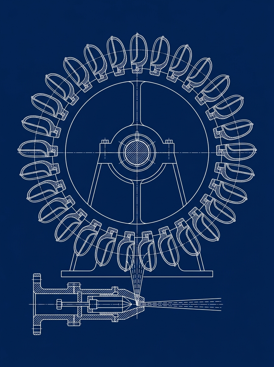
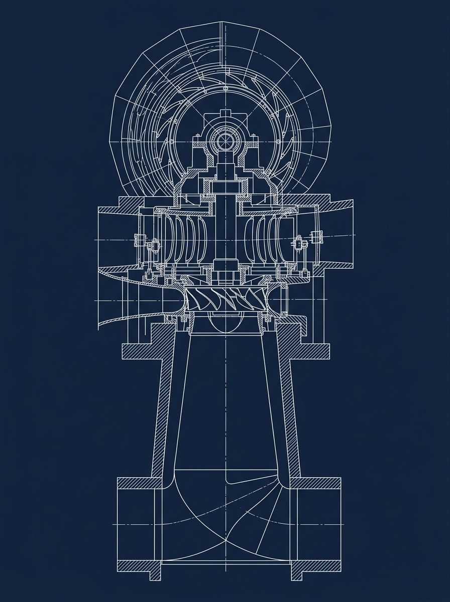
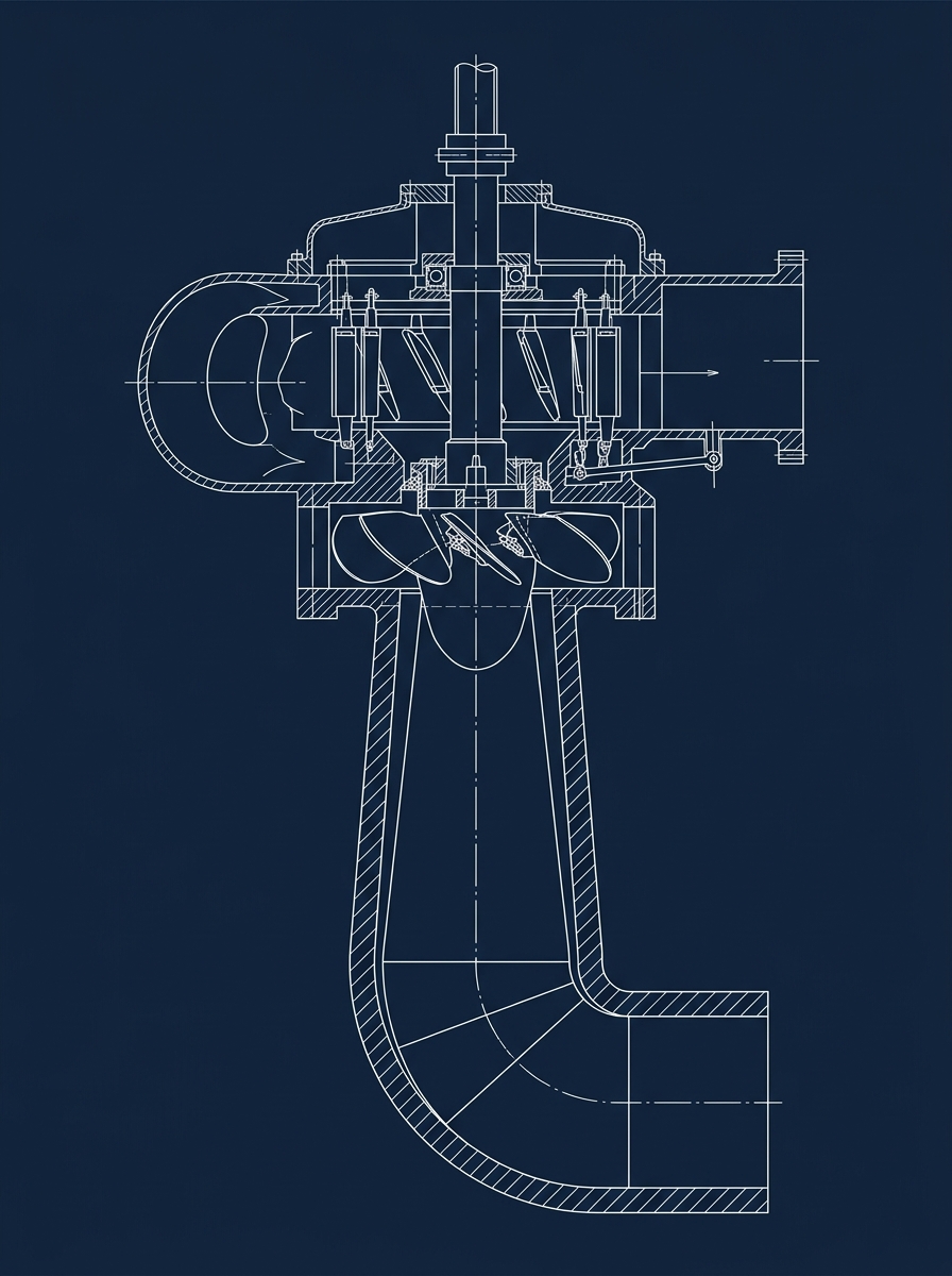
Hydraulic Turbines
Presented by: Ishaan <span style="font-size: 18px; opacity: 0.8;">(Roll No. 42)</span>
MET001 | Fluid Mechanics and Thermodynamics Fundamentals
PELTON TURBINE
<strong style="color:#FFFFFF;">Impulse Turbine</strong> | High head (>300m) | Low flow rate
FRANCIS TURBINE
<strong style="color:#FFFFFF;">Mixed-flow Turbine</strong> | Medium head (40–600m)
KAPLAN TURBINE
<strong style="color:#FFFFFF;">Axial-flow Turbine</strong> | Low head (<40m) | High flow rate
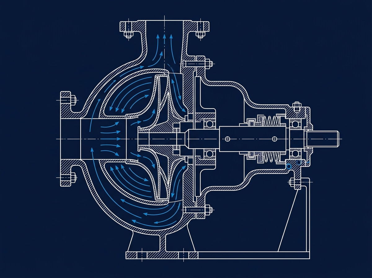
Centrifugal Pump
08
Presented by: Ishant (Roll No. 43)
CONSTRUCTION
Consists of impeller enclosed in volute casing, inlet eye, discharge nozzle, shaft, and bearings. Casing is spiral-shaped (volute) to convert velocity to pressure.
WORKING PRINCIPLE
Centrifugal force imparted to fluid by rotating impeller. Fluid enters axially at eye, exits radially at high velocity. Velocity energy converted to pressure in volute casing.
MAIN COMPONENTS
Impeller (rotating)
Volute Casing
Suction Pipe & Strainer
Delivery Pipe & Valve
Shaft & Bearings
Stuffing Box / Seal
Impeller
Volute Casing
Eye/Inlet
Discharge
Shaft
Blade/Vane
Stuffing Box
MET001 | Fluid Mechanics and Thermodynamics Fundamentals
09
Reciprocating Pump
Presented by: Ishant (Roll No. 43)
Piston/plunger inside a cylinder with <strong>suction valve</strong>, <strong>delivery valve</strong>, and connecting pipes. It is driven mechanically by a crank-connecting rod mechanism.
A positive displacement pump. The piston reciprocates (moves back-and-forth) to create alternating suction and delivery. Valves automatically control the one-way fluid flow direction.
Piston retracts <span style="color:#5DADE2; font-weight:bold;">→</span> Volume increases <span style="color:#5DADE2; font-weight:bold;">→</span> Pressure drops <span style="color:#5DADE2; font-weight:bold;">→</span> Suction valve opens <span style="color:#5DADE2; font-weight:bold;">→</span> Fluid drawn in
Piston advances <span style="color:#F39C12; font-weight:bold;">→</span> Volume decreases <span style="color:#F39C12; font-weight:bold;">→</span> Pressure rises <span style="color:#F39C12; font-weight:bold;">→</span> Delivery valve opens <span style="color:#F39C12; font-weight:bold;">→</span> Fluid forced out
MET001 | Fluid Mechanics and Thermodynamics Fundamentals
10
Zeroth Law of Thermodynamics
Presented by: Jatin (Roll No. 44)
"If two thermodynamic systems are each in thermal equilibrium with a third system, then they are in thermal equilibrium with each other."
Two bodies are in thermal equilibrium when <strong style="color: #FFFFFF; font-weight: 600;">no heat flows between them</strong> — i.e., they are at the <strong style="color: #F39C12; font-weight: 600;">SAME TEMPERATURE</strong>.
<ul style="margin: 0; padding-left: 25px; display: flex; flex-direction: column; gap: 14px;"><li><strong style="color: #FFFFFF; font-weight: 500;">Provides the scientific basis</strong> for temperature measurement</li><li><strong style="color: #FFFFFF; font-weight: 500;">Allows thermometers to work</strong> — thermometer (System C) reaches equilibrium with body A and body B independently</li><li><strong style="color: #FFFFFF; font-weight: 500;">Foundation</strong> for defining temperature as a thermodynamic property</li></ul>
MET001 | Fluid Mechanics and Thermodynamics Fundamentals
11
First Law of Thermodynamics
Presented by: Jatin (Roll No. 44)
Q = ΔU + W
Q = Heat added to system | ΔU = Change in Internal Energy | W = Work done by system
PRINCIPLE
Energy cannot be created or destroyed — only converted from one form to another. The total energy of an isolated system remains constant.
SIGN CONVENTION
<div style="display: flex; flex-direction: column; gap: 16px; font-size: 18px;"> <div style="display: flex; gap: 15px; align-items: center;"> <div style="width: 130px; background-color: #0D1B2A; padding: 10px; border-radius: 6px; border-left: 4px solid #F39C12; font-weight: bold; color: #F39C12; text-align: center; box-shadow: inset 0 2px 4px rgba(0,0,0,0.5);">+ Q</div> <div style="font-weight: 300;">Heat added to system</div> </div> <div style="display: flex; gap: 15px; align-items: center;"> <div style="width: 130px; background-color: #0D1B2A; padding: 10px; border-radius: 6px; border-left: 4px solid #E74C3C; font-weight: bold; color: #E74C3C; text-align: center; box-shadow: inset 0 2px 4px rgba(0,0,0,0.5);">- Q</div> <div style="font-weight: 300;">Heat rejected by system</div> </div> <div style="display: flex; gap: 15px; align-items: center;"> <div style="width: 130px; background-color: #0D1B2A; padding: 10px; border-radius: 6px; border-left: 4px solid #2ECC71; font-weight: bold; color: #2ECC71; text-align: center; box-shadow: inset 0 2px 4px rgba(0,0,0,0.5);">+ W</div> <div style="font-weight: 300;">Work done by system</div> </div> <div style="display: flex; gap: 15px; align-items: center;"> <div style="width: 130px; background-color: #0D1B2A; padding: 10px; border-radius: 6px; border-left: 4px solid #95A5A6; font-weight: bold; color: #95A5A6; text-align: center; box-shadow: inset 0 2px 4px rgba(0,0,0,0.5);">- W</div> <div style="font-weight: 300;">Work done on system</div> </div> </div>
FORMS OF ENERGY
<div style="display: flex; flex-direction: column; gap: 12px; font-size: 20px; font-weight: 300;"> <div style="display: flex; align-items: center; gap: 15px;"> <div style="width: 8px; height: 8px; background-color: #F39C12; border-radius: 50%; box-shadow: 0 0 5px #F39C12;"></div> <div>Internal Energy (<b style="color: #F39C12; font-weight: 600;">U</b>)</div> </div> <div style="display: flex; align-items: center; gap: 15px;"> <div style="width: 8px; height: 8px; background-color: #F39C12; border-radius: 50%; box-shadow: 0 0 5px #F39C12;"></div> <div>Heat Transfer (<b style="color: #F39C12; font-weight: 600;">Q</b>)</div> </div> <div style="display: flex; align-items: center; gap: 15px;"> <div style="width: 8px; height: 8px; background-color: #F39C12; border-radius: 50%; box-shadow: 0 0 5px #F39C12;"></div> <div>Work Done (<b style="color: #F39C12; font-weight: 600;">W</b>)</div> </div> </div>
MET001 | Fluid Mechanics and Thermodynamics Fundamentals
Flow and Non-Flow Processes
Presented by: Jatin (Roll No. 44)
MET001 | Fluid Mechanics and Thermodynamics Fundamentals
13
Flow Work and Non-Flow Work
Presented by: Jatin (Roll No. 44)
FLOW WORK (Flow Energy)
Work done by fluid to push a mass element across the system boundary into or out of a control volume.
W<sub>flow</sub> = PV = Pv <span style="font-size: 22px; font-weight: 300; color: #ECF0F1; font-family: 'Helvetica Neue', Helvetica, Arial, sans-serif;">(per unit mass)</span>
where P = pressure, v = specific volume
<li style="margin-bottom: 12px;">Occurs in open systems</li><li style="margin-bottom: 12px;">Associated with mass transport</li><li style="margin-bottom: 12px;">Part of enthalpy: <span style="font-family: monospace; color: #F39C12; font-weight: 500;">h = u + Pv</span></li><li style="margin-bottom: 0;">Present in turbines, compressors, nozzles</li>
NON-FLOW WORK (Boundary Work)
Work done by or on a system due to the movement of the system boundary (e.g., piston displacement).
W = ∫ P dV
displacement work in a closed system
<li style="margin-bottom: 12px;">Occurs in closed systems</li><li style="margin-bottom: 12px;">Piston-cylinder processes</li><li style="margin-bottom: 12px;">Area under P-V diagram = work done</li><li style="margin-bottom: 0;">Present in IC engines, steam engines</li>
MET001 | Fluid Mechanics and Thermodynamics Fundamentals
14
Steady Flow Energy Equation (SFEE)
Presented by: Kamal (Roll No. 45)
Q - W = (h₂ - h₁) + ½(V₂² - V₁²) + g(z₂ - z₁)
<span style="color:#F39C12; font-weight:bold;">Q</span> = Heat transfer | <span style="color:#3498DB; font-weight:bold;">W</span> = Work transfer | <span style="font-weight:bold;">h</span> = Specific enthalpy | <span style="font-weight:bold;">V</span> = Velocity | <span style="font-weight:bold;">z</span> = Elevation | <span style="font-weight:bold;">g</span> = Gravity
SFEE applies to open systems with steady flow — mass flow rate is constant. It represents the comprehensive energy balance for a control volume through which fluid flows steadily.
<div style="display: flex; gap: 15px; align-items: flex-start;"> <div style="width: 32px; height: 32px; background-color: #1B4F72; border-radius: 50%; display: flex; justify-content: center; align-items: center; color: #FFFFFF; font-size: 16px; font-weight: bold; flex-shrink: 0; margin-top: 2px;">1</div> <div><span style="color: #F39C12; font-weight: bold; font-family: monospace; font-size: 26px;">Q</span> → Heat added per unit mass</div> </div> <div style="display: flex; gap: 15px; align-items: flex-start;"> <div style="width: 32px; height: 32px; background-color: #1B4F72; border-radius: 50%; display: flex; justify-content: center; align-items: center; color: #FFFFFF; font-size: 16px; font-weight: bold; flex-shrink: 0; margin-top: 2px;">2</div> <div><span style="color: #F39C12; font-weight: bold; font-family: monospace; font-size: 26px;">W</span> → Shaft work per unit mass</div> </div> <div style="display: flex; gap: 15px; align-items: flex-start;"> <div style="width: 32px; height: 32px; background-color: #1B4F72; border-radius: 50%; display: flex; justify-content: center; align-items: center; color: #FFFFFF; font-size: 16px; font-weight: bold; flex-shrink: 0; margin-top: 2px;">3</div> <div><span style="color: #F39C12; font-weight: bold; font-family: monospace; font-size: 26px;">h₂ - h₁</span> → Enthalpy change <br><span style="font-size: 18px; color: #95A5A6;">(Flow work + internal energy)</span></div> </div> <div style="display: flex; gap: 15px; align-items: flex-start;"> <div style="width: 32px; height: 32px; background-color: #1B4F72; border-radius: 50%; display: flex; justify-content: center; align-items: center; color: #FFFFFF; font-size: 16px; font-weight: bold; flex-shrink: 0; margin-top: 2px;">4</div> <div><span style="color: #F39C12; font-weight: bold; font-family: monospace; font-size: 26px;">½(V₂² - V₁²)</span> → Kinetic energy change</div> </div> <div style="display: flex; gap: 15px; align-items: flex-start;"> <div style="width: 32px; height: 32px; background-color: #1B4F72; border-radius: 50%; display: flex; justify-content: center; align-items: center; color: #FFFFFF; font-size: 16px; font-weight: bold; flex-shrink: 0; margin-top: 2px;">5</div> <div><span style="color: #F39C12; font-weight: bold; font-family: monospace; font-size: 26px;">g(z₂ - z₁)</span> → Potential energy change</div> </div>
SFEE is the open-system equivalent of the First Law. It extends the energy conservation principle to continuous flow processes.
<div style="display: flex; gap: 18px; width: 100%;"> <div style="flex: 1; display: flex; flex-direction: column; align-items: center; justify-content: center; gap: 10px; border: 1px solid rgba(243, 156, 18, 0.4); border-radius: 8px; padding: 15px 10px; background-color: rgba(13, 27, 42, 0.6); box-shadow: 0 4px 10px rgba(0,0,0,0.2);"> <svg width="40" height="40" viewBox="0 0 24 24" fill="none" stroke="#F39C12" stroke-width="2" stroke-linecap="round" stroke-linejoin="round"><circle cx="12" cy="12" r="10"></circle><path d="M12 2A10 10 0 0 1 22 12"></path><line x1="12" y1="2" x2="12" y2="12"></line><line x1="22" y1="12" x2="12" y2="12"></line><line x1="5" y1="19" x2="12" y2="12"></line></svg> <div style="color: #FFFFFF; font-size: 15px; font-weight: bold; text-transform: uppercase; letter-spacing: 1px;">Turbine</div> </div> <div style="flex: 1; display: flex; flex-direction: column; align-items: center; justify-content: center; gap: 10px; border: 1px solid rgba(243, 156, 18, 0.4); border-radius: 8px; padding: 15px 10px; background-color: rgba(13, 27, 42, 0.6); box-shadow: 0 4px 10px rgba(0,0,0,0.2);"> <svg width="40" height="40" viewBox="0 0 24 24" fill="none" stroke="#F39C12" stroke-width="2" stroke-linecap="round" stroke-linejoin="round"><polygon points="4 2 20 6 20 18 4 22 4 2"></polygon><line x1="8" y1="6" x2="8" y2="18"></line><line x1="16" y1="8" x2="16" y2="16"></line></svg> <div style="color: #FFFFFF; font-size: 15px; font-weight: bold; text-transform: uppercase; letter-spacing: 1px;">Compressor</div> </div> <div style="flex: 1; display: flex; flex-direction: column; align-items: center; justify-content: center; gap: 10px; border: 1px solid rgba(243, 156, 18, 0.4); border-radius: 8px; padding: 15px 10px; background-color: rgba(13, 27, 42, 0.6); box-shadow: 0 4px 10px rgba(0,0,0,0.2);"> <svg width="40" height="40" viewBox="0 0 24 24" fill="none" stroke="#F39C12" stroke-width="2" stroke-linecap="round" stroke-linejoin="round"><path d="M22 12h-6l-8-8H2v16h6l8-8"></path><line x1="18" y1="12" x2="22" y2="12"></line></svg> <div style="color: #FFFFFF; font-size: 15px; font-weight: bold; text-transform: uppercase; letter-spacing: 1px;">Nozzle</div> </div> <div style="flex: 1; display: flex; flex-direction: column; align-items: center; justify-content: center; gap: 10px; border: 1px solid rgba(243, 156, 18, 0.4); border-radius: 8px; padding: 15px 10px; background-color: rgba(13, 27, 42, 0.6); box-shadow: 0 4px 10px rgba(0,0,0,0.2);"> <svg width="40" height="40" viewBox="0 0 24 24" fill="none" stroke="#F39C12" stroke-width="2" stroke-linecap="round" stroke-linejoin="round"><rect x="4" y="4" width="16" height="16" rx="2" ry="2"></rect><path d="M4 14h16"></path><path d="M12 22v-8"></path><path d="M8 4v-2"></path><path d="M16 4v-2"></path></svg> <div style="color: #FFFFFF; font-size: 15px; font-weight: bold; text-transform: uppercase; letter-spacing: 1px;">Boiler</div> </div> </div>
MET001 | Fluid Mechanics and Thermodynamics Fundamentals
15
Summary
Fluid Mechanics & Thermodynamics Fundamentals | MET001
FLUID PROPERTIES
Density · Specific Gravity · Viscosity · Surface Tension
Foundation
TYPES OF FLUIDS
Ideal · Real · Newtonian · Non-Newtonian · Compressible · Incompressible
Classification
FLUID LAWS
Pascal's Law · Newton's Law · Bernoulli's Equation
Laws
HYDRAULIC MACHINES
Hydraulic Turbines · Centrifugal Pump · Reciprocating Pump
Applications
THERMODYNAMICS
Zeroth Law · First Law · Flow & Non-Flow Processes
Energy Principles
SFEE
Steady Flow Energy Equation — Unifying Principle
Unified Equation
MET001 | Fluid Mechanics and Thermodynamics Fundamentals | First Year Mechanical Engineering
Thank You
Questions & Discussion
We welcome your questions and feedback
<span style="color: #F39C12; font-weight: 600;">Course:</span> Basic Mechanical Engineering (MET001)<br><span style="color: #F39C12; font-weight: 600;">Topic:</span> Fluid Mechanics and Thermodynamics Fundamentals<br><span style="color: #F39C12; font-weight: 600;">Year:</span> First Year Mechanical Engineering | 2025–26
<span style="opacity: 0.6;">Roll No. 38</span> — Diya<br><span style="opacity: 0.6;">Roll No. 39</span> — Geeta<br><span style="opacity: 0.6;">Roll No. 40</span> — Harshit<br><span style="opacity: 0.6;">Roll No. 42</span> — Ishaan
<span style="opacity: 0.6;">Roll No. 43</span> — Ishant<br><span style="opacity: 0.6;">Roll No. 44</span> — Jatin<br><span style="opacity: 0.6;">Roll No. 45</span> — Kamal
MET001 | Fluid Mechanics and Thermodynamics Fundamentals | Basic Mechanical Engineering
- mechanical-engineering
- fluid-mechanics
- thermodynamics
- bernoulli-equation
- pascals-law
- hydraulic-turbines
- sfee
- physics