Transformers: Construction, Working Principles & Applications
Comprehensive guide to Class 12 Physics transformers: learn about mutual induction, step-up vs step-down types, core construction, and efficiency losses.
TRANSFORMERS
Class 12 Physics | Electromagnetic Induction & Alternating Current
Introduction to Transformers
The transformer is an essential static device in Alternating Current (AC) transmission systems that transfers electrical energy between circuits without moving parts. Its invention enabled feasible long-distance power transmission by minimizing energy loss. Operating on principles discovered by Faraday and Henry, it functions exclusively with AC voltage.
Definition & Principle
A transformer is defined as a device used to increase or decrease the voltage of an alternating current supply. It operates on the principle of Mutual Induction. When a changing current flows through the primary coil, it generates a changing magnetic flux that links with the secondary coil, inducing an EMF in the secondary according to Faraday's Law, all while maintaining the same frequency.
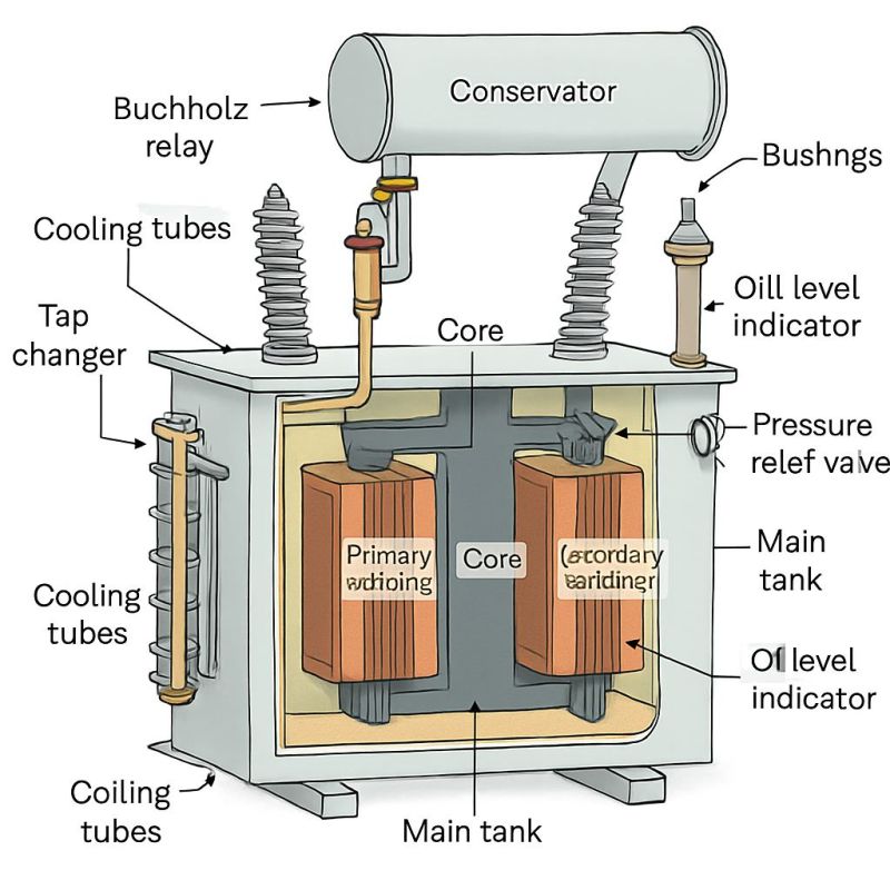
Construction of Transformer
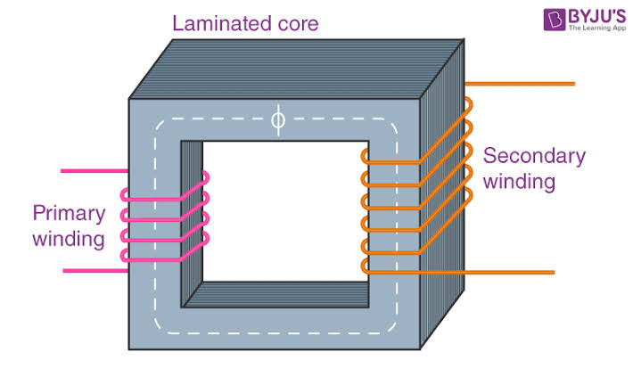
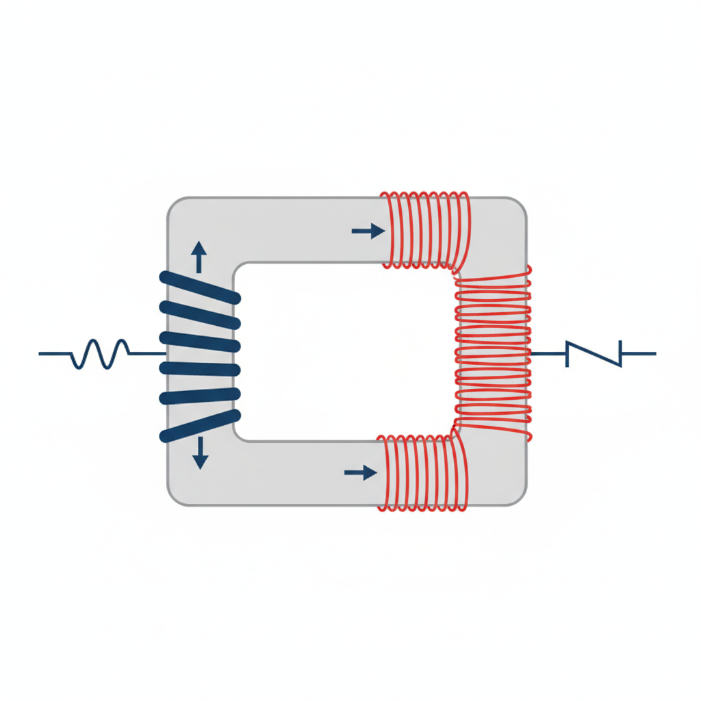
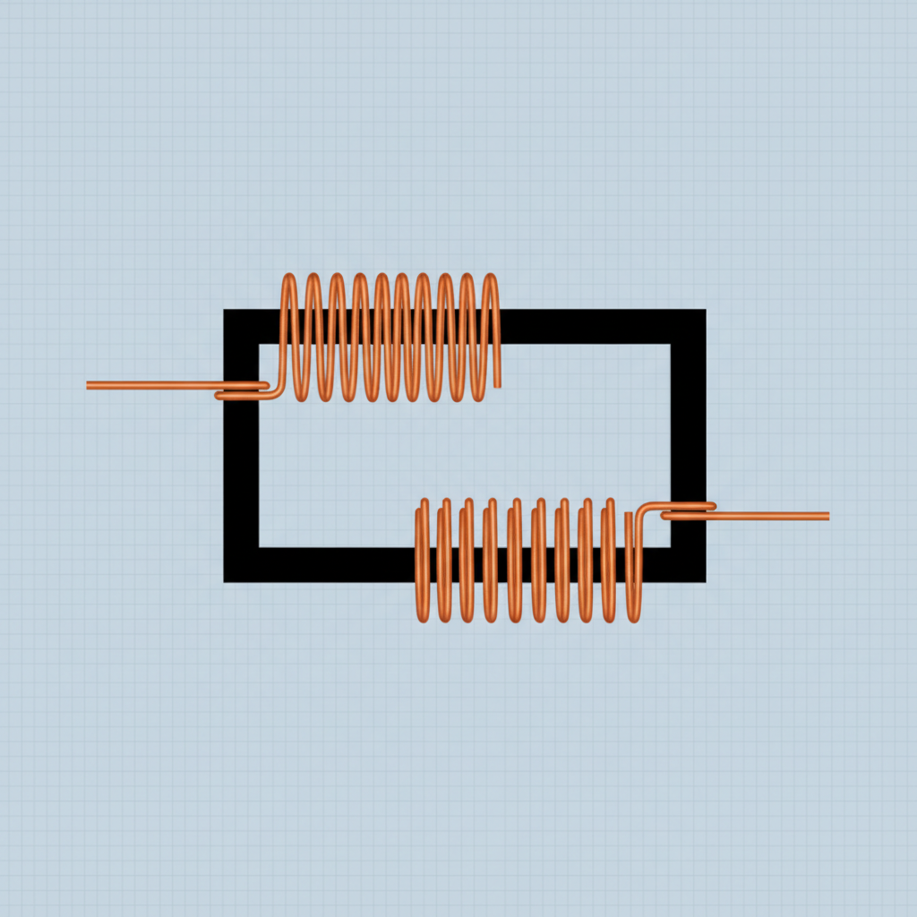
A transformer primarily consists of two electrically isolated coils wound on a common magnetic core.
Basic Parts: Magnetic Core, Primary Winding, and Secondary Winding.
The core provides a low reluctance path for the magnetic flux.
The windings are made of insulated copper wire to minimize resistance.
Types of Core Construction: Core-type (windings surround core) and Shell-type (core surrounds windings).
Insulation is critical to prevent short circuits between turns and the core.
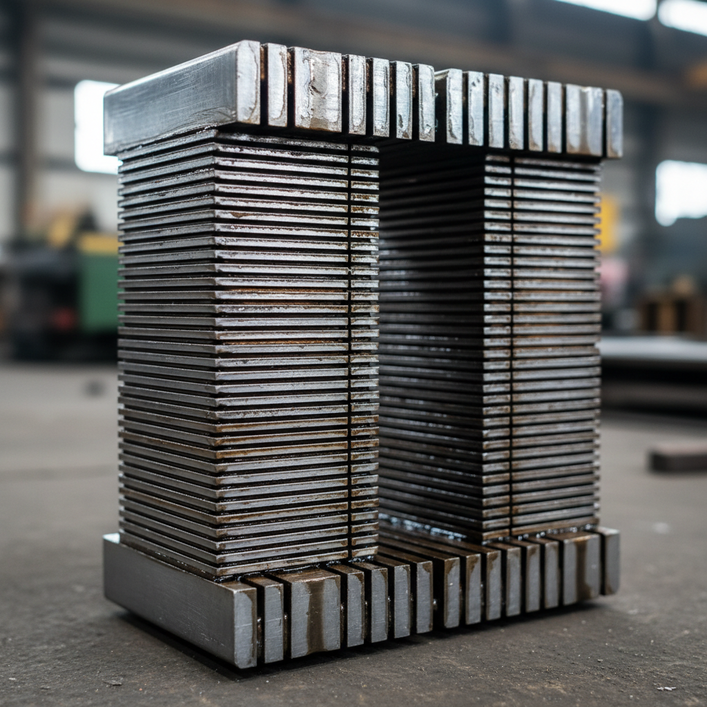
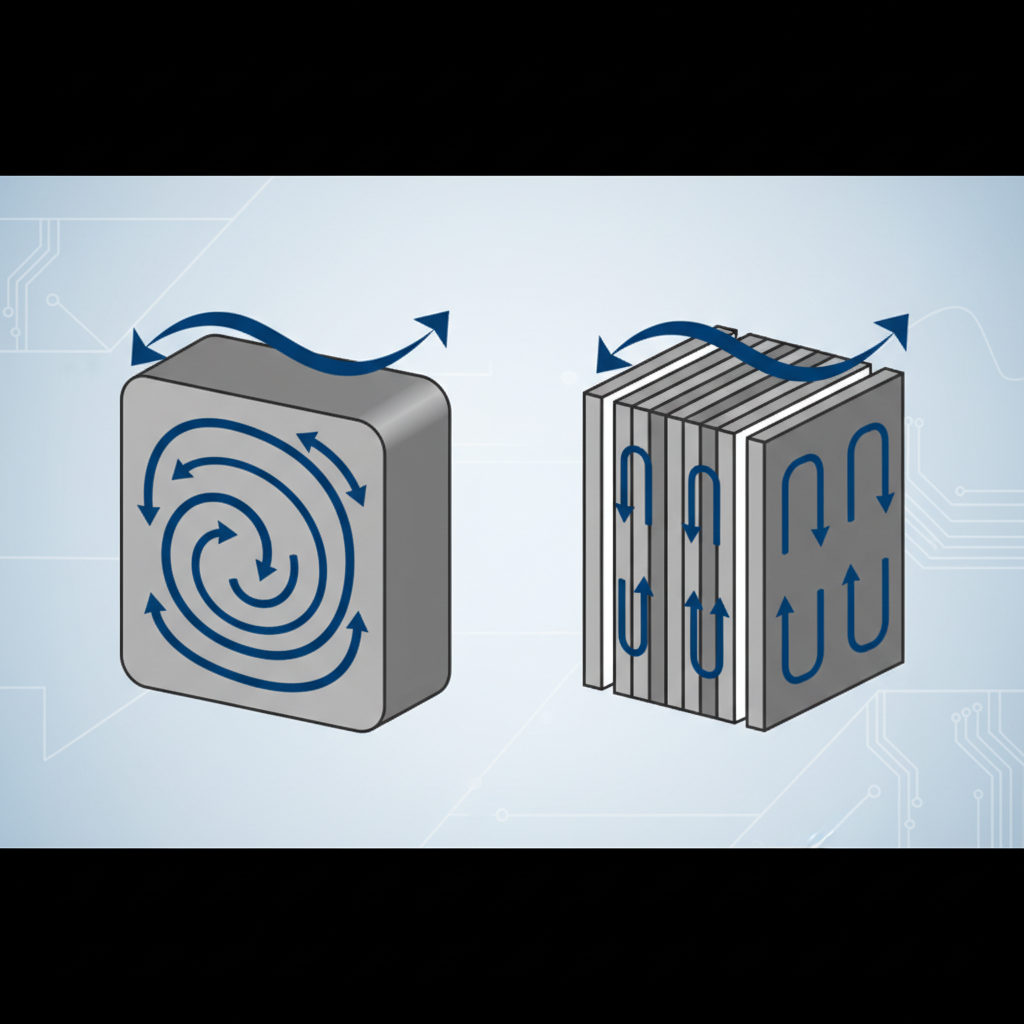
The Core: Soft Iron & Lamination
• Material: The core is made of soft iron or silicon steel. • High Permeability: Soft iron is used to ensure high magnetic permeability and low hysteresis. • Laminated Core: The core is not a solid block but a stack of thin sheets (laminations). • Reason for Lamination: To minimize Eddy Current loss. • Insulation: Each lamination is insulated from the other by a thin layer of varnish. • Function: Increases efficiency by reducing heat generation.
Working of Transformer
• An alternating voltage source is connected to the primary winding to start the process. • This voltage drives an AC current that generates a sinusoidally varying magnetic flux. • The magnetic flux is confined within the high-permeability soft iron core. • Flux travels through the core and links effectively with the secondary winding. • According to Faraday's Law, a changing magnetic flux induces an EMF in the secondary coil. • This phenomenon is called Mutual Induction; energy transfers magnetically without electrical contact. • If the secondary circuit is closed, an induced current flows through the load. • The frequency of the induced output voltage is the same as the input frequency.
EMF Equation of Transformer
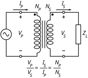
Let Nₚ and Nₛ be the number of turns in primary and secondary coils. Let φ be the magnetic flux linkage. • Induced EMF in Primary: Eₚ = -Nₚ (dφ/dt) • Induced EMF in Secondary: Eₛ = -Nₛ (dφ/dt) • Assuming ideal conditions (no resistance): Eₚ ≈ Vₚ and Eₛ ≈ Vₛ • Input Voltage matches Primary Back EMF. • Output Voltage depends on the rate of change of flux and secondary turns.
Voltage Transformation Ratio (k)
Dividing the secondary EMF equation by the primary EMF equation gives the ratio.
Formula: Vₛ / Vₚ = Nₛ / Nₚ = k
'k' is known as the Transformation Ratio.
For Ideal Transformer: Input Power = Output Power (VₚIₚ = VₛIₛ).
Current Ratio: Iₚ / Iₛ = Nₛ / Nₚ = k
Voltage and Current are inversely proportional.
<ul><li>Dividing the secondary EMF equation by the primary EMF equation gives the ratio.</li><li style='font-weight:bold; color:#d35400;'>Formula: Vₛ / Vₚ = Nₛ / Nₚ = k</li><li>'k' is known as the Transformation Ratio.</li><li>For Ideal Transformer: Input Power = Output Power (VₚIₚ = VₛIₛ).</li><li style='font-weight:bold; color:#d35400;'>Current Ratio: Iₚ / Iₛ = Nₛ / Nₚ = k</li><li>Voltage and Current are inversely proportional.</li></ul>
Step-Up Transformer
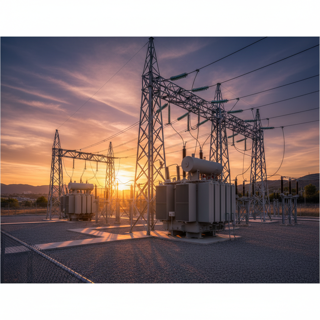
• Function: Increases the alternating voltage. • Turn Relation: Nₛ > Nₚ (Secondary turns > Primary turns). • Transformation Ratio: k > 1. • Voltage/Current: Increases voltage, decreases current. • Output: Vₛ > Vₚ and Iₛ < Iₚ. • Uses: Used at power generating stations to step up voltage for long-distance transmission.
Step-Down Transformer
• Function: Decreases the alternating voltage. • Turn Relation: Nₛ < Nₚ (Secondary turns < Primary turns). • Transformation Ratio: k < 1. • Voltage/Current: Decreases voltage, increases current. • Output: Vₛ < Vₚ and Iₛ > Iₚ. • Uses: Used in household distribution, mobile chargers, and welding machines.
Ideal Transformer
An ideal transformer is a theoretical concept with 100% efficiency.
Assumption 1: Zero winding resistance (no copper loss).
Assumption 2: No magnetic flux leakage (all flux links both coils).
Assumption 3: Infinite core permeability (no magnetizing current needed).
Assumption 4: Zero core losses (no hysteresis or eddy current).
In practice, no transformer is truly ideal, though many approach high efficiency.
<ul style='list-style-type:circle; padding-left:30px;'> <li>An ideal transformer is a theoretical concept with 100% efficiency.</li> <li>Assumption 1: Zero winding resistance (no copper loss).</li> <li>Assumption 2: No magnetic flux leakage (all flux links both coils).</li> <li>Assumption 3: Infinite core permeability (no magnetizing current needed).</li> <li>Assumption 4: Zero core losses (no hysteresis or eddy current).</li> <li>In practice, no transformer is truly ideal, though many approach high efficiency.</li> </ul>
Losses in a Transformer
Real transformers have energy losses, meaning Output Power < Input Power. These losses appear as heat and vibration. There are four main types of losses: 1. Flux Leakage 2. Resistance / Copper Loss 3. Eddy Current Loss 4. Hysteresis Loss
1. Flux Leakage & 2. Copper Loss
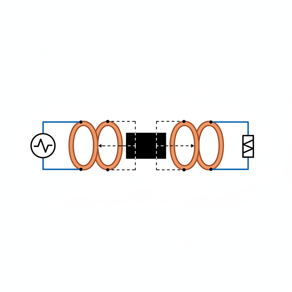
Flux Leakage: Not all flux produced by the primary passes through the secondary due to poor core design or air gaps.
Remedy (Flux): Use a high permeability soft iron core.
Copper Loss: Energy dissipated as heat (I²R) in the copper windings.
Cause: Resistance of the wire used for windings.
Remedy (Copper): Use thick copper wires for high current windings to reduce resistance.
3. Eddy Current & 4. Hysteresis Loss
• Eddy Currents: Changing magnetic flux induces small circulating currents in the iron core, causing heating. • Remedy: Use a laminated core. • Hysteresis Loss: The core is repeatedly magnetized and demagnetized by AC. • Energy is lost as heat during each cycle of magnetization. • Remedy: Use soft iron, which has low retentivity and low coercivity (narrow Hysteresis loop).
Efficiency of Transformer
• Efficiency (η) is the ratio of Output Power to Input Power. • Formula: η = (Output Power) / (Output Power + Losses) × 100%. • Transformers are highly efficient devices (90% - 99%). • Efficiency is not constant; it depends on the load. • Maximum efficiency occurs when Copper Loss = Iron Loss.
Uses of Transformer
Power Transmission: Boosting voltage for long distance transmission to reduce I²R losses.
Voltage Regulation: Used in stabilizers to maintain constant voltage.
Electronics: Small step-down transformers in chargers, radios, and TV power supplies.
Welding: Step-down transformers produce high current required for welding.
Induction Furnaces: Used for melting metals.
Audio: Impedance matching in audio systems.
Questions & Answers
Q: Can a transformer work on DC? A: No. DC produces constant flux, so no EMF is induced. It may burn the winding.
Q: Why is the core laminated? A: To reduce invalid eddy currents and associated heat loss.
Q: Does the frequency change in a transformer? A: No, the frequency of input and output AC remains the same.
Q: What is the efficiency of a practical transformer? A: Typically between 90% and 99%.
Conclusion
Transformers are indispensable components of modern AC electrical networks, facilitating efficient long-distance power transmission through their simple, robust construction. By understanding and minimizing losses, engineers can design high-efficiency units that power everything from massive substations to small electronics. Mastery of these principles is crucial for understanding electrical infrastructure in Class 12 Physics.
- transformers
- physics-notes
- mutual-induction
- electrical-engineering
- step-down-transformer
- step-up-transformer
- class-12-physics