
Transformers in Physics: Principles and Applications
Learn how transformers work, including mutual induction, step-up vs. step-down types, core construction, and efficiency in power distribution.
TRANSFORMERS
Class 12 Physics Presentation
Introduction
Electric power is generated at power stations at relatively low voltages (e.g., 11kV).
For transmission over long distances, voltage must be stepped up to reduce distribution losses (I²R).
At the consumer end, high voltage must be stepped down for safety and appliance compatibility.
The device that makes this voltage regulation possible is the Transformer.
It plays a pivotal role in the alternating current (AC) distribution system worldwide.
Transformers operate only on AC, not on Direct Current (DC).
Definition of Transformer
A transformer is a static electrical device used to change the alternating voltage from one value to another without changing the frequency. It transfers electrical energy from one circuit to another circuit through the medium of a magnetic field.
Device Type: Static (no moving parts).
Key Function: Steps voltage up or down.
Conservation: Power remains (ideally) constant.
Frequency: Remains unchanged (f_in = f_out).
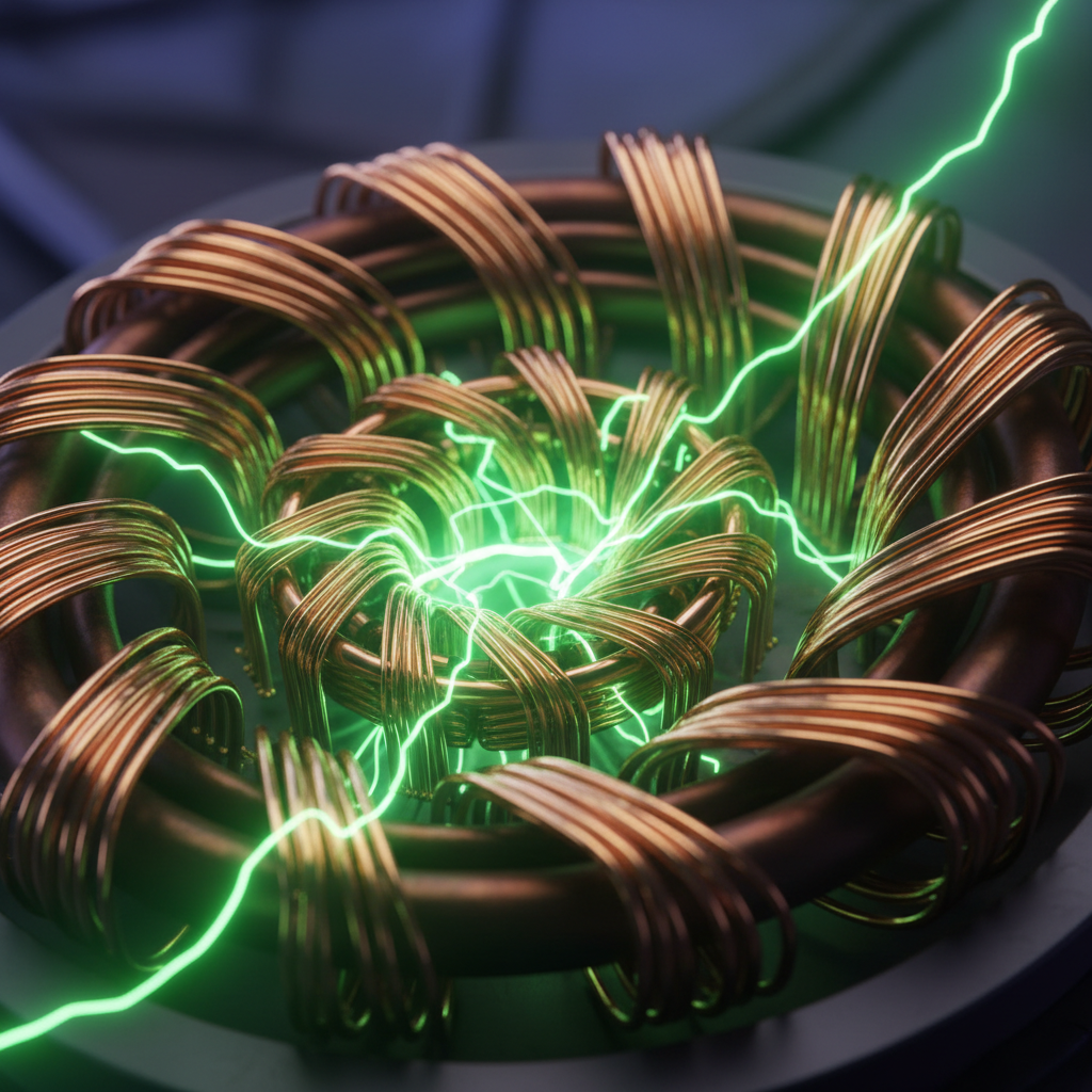
Principle of Transformer
A transformer operates on the principle of Mutual Induction.
Mutual Induction states that when a changing current flows through one coil (Primary), it creates a changing magnetic flux.
This varying magnetic flux links with the second coil (Secondary) placed nearby.
According to Faraday's Law of Electromagnetic Induction, an EMF is induced in the secondary coil.
The two coils are magnetically coupled but electrically isolated.
The magnitude of induced EMF depends on the rate of change of flux and number of turns.
Construction of Transformer
A transformer primarily consists of three main parts.
Primary Winding: Connected to the source supply.
Secondary Winding: Connected to the load circuit.
Laminated Magnetic Core: Provides a low reluctance path for magnetic flux.
The coils are insulated from each other and from the core.
The choice of material (usually copper) helps in minimizing resistance losses.
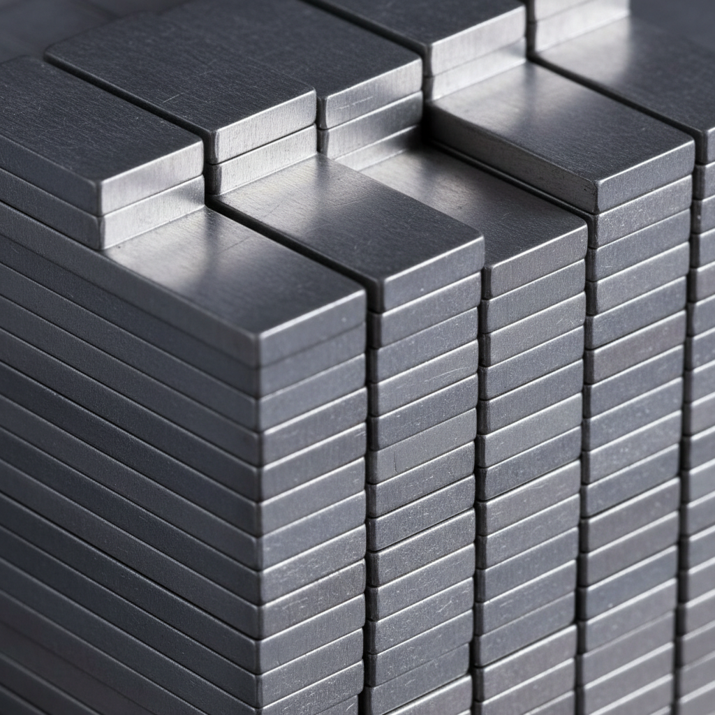
The Laminated Core
Material: Made of Soft Iron or Silicon Steel to ensure high permeability.
High permeability allows magnetic flux to flow easily through the core.
Low Retentivity: Reduces hysteresis loss (energy lost in magnetization cycles).
Structure: The core is NOT a solid block of metal.
Lamination: It is made of thin rectangular strips stamped together.
Insulation: Strips are coated with varnish to reduce Eddy Current losses.
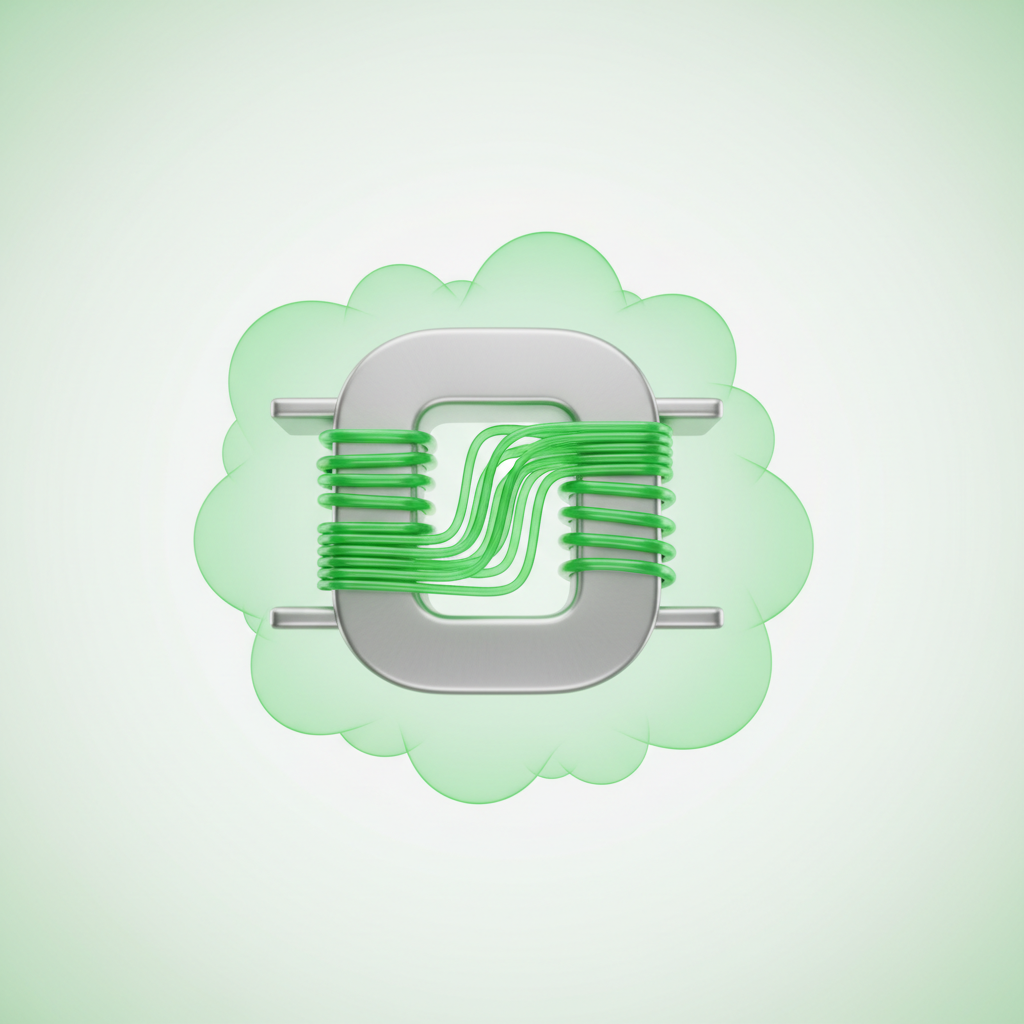
Primary and Secondary Windings
The windings are simply coils of wire wound around the transformer core.
Material: Usually Copper, due to its low resistivity and high conductivity.
Np represents the number of turns in the Primary winding.
Ns represents the number of turns in the Secondary winding.
The voltage ratio is directly proportional to the ratio of turns (Ns/Np).
Heavy gauge wire is used for high current windings to prevent overheating.
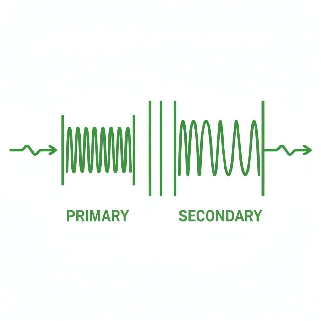
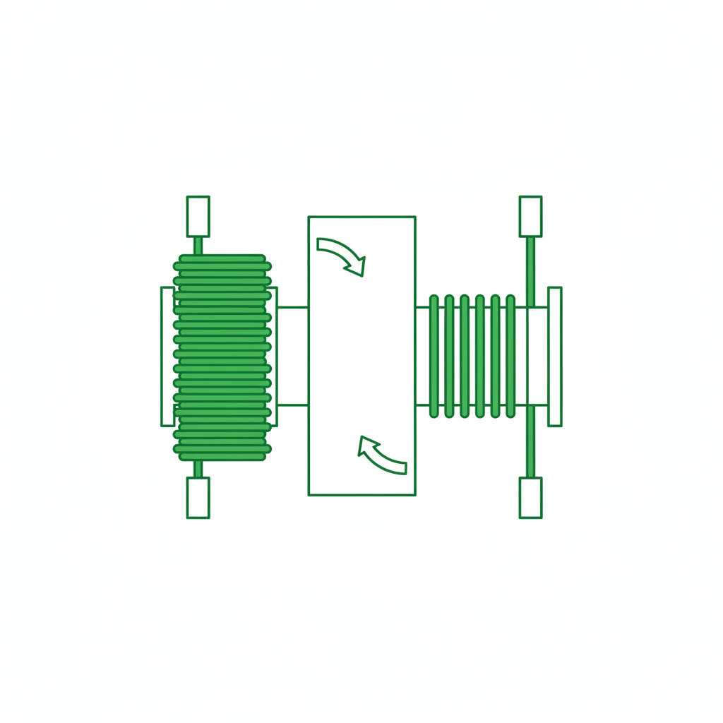
Diagrammatic Representation of a Transformer
Working of Transformer
An alternating source of voltage (Vp) is applied to the primary coil.
This causes an alternating current (Ip) to flow in the primary circuit.
The periodic current produces a continuously changing magnetic flux (Φ) in the core.
This magnetic flux travels through the soft iron core and links with the secondary coil.
Due to the change in flux linkage, an induced EMF (Es) is generated in the secondary coil.
If the secondary circuit is closed, current (Is) flows to the load.
EMF Equation of Transformer
According to Faraday's Law: E = -N (dΦ/dt).
Assume flux Φ = Φm sin(ωt). The induced EMF lags flux by 90 degrees.
The RMS value of induced EMF is given by the equation:
E = 4.44 f N Φm
Where 'f' is the frequency of AC supply.
'N' is the number of turns in the respective winding.
'Φm' is the maximum flux in the core (Webers).
Voltage Transformation Ratio (k)
The ratio of secondary voltage to primary voltage is constant.
Transformation Ratio 'k' = Vs / Vp = Ns / Np
For an ideal transformer, Input Power = Output Power (Vp Ip = Vs Is).
Therefore, current ratio is inverse: Ip / Is = k.
Complete Relation: Vs/Vp = Ip/Is = Ns/Np = k.
This 'k' factor determines if the transformer is Step-up or Step-down.
Step-up Transformer
A step-up transformer increases the voltage from primary to secondary. This is achieved by having more turns on the secondary coil than on the primary coil.
Condition: Ns > Np
Transformation Ratio: k > 1
Output: High Voltage, Low Current.
Application: Used at Power Generating Stations to boost voltage for transmission.
Step-down Transformer
A step-down transformer decreases the voltage from primary to secondary. It has fewer turns on the secondary coil compared to the primary coil.
Condition: Np > Ns
Transformation Ratio: k < 1
Output: Low Voltage, High Current.
Application: Mobile chargers, electrical substations, welding machines.
Characteristics of an Ideal Transformer
An ideal transformer is a theoretical concept with 100% efficiency.
Zero Winding Resistance: The primary and secondary coils have no internal resistance (no Copper loss).
No Flux Leakage: All magnetic flux produced by the primary links with the secondary.
Infinite Permeability: The core requires negligible MMF to set up flux.
No Iron Losses: Hysteresis and eddy current losses are zero.
In reality, ideal transformers do not exist, but modern transformers can reach 99% efficiency.
Losses: Copper Loss
Cause: The windings (Primary and Secondary) have finite resistance (R).
Mechanism: When current (I) flows, heat is produced due to Joule's heating effect.
Formula: Power Loss = I²R.
This is a 'Variable Loss' because it depends on the load current.
Minimization: Using thick copper wires for high current windings to reduce resistance.
Copper loss usually constitutes the largest portion of full-load losses.
Losses: Iron Loss (Core Loss)
Iron losses occur in the magnetic core and are generally constant regardless of load.
These are divided into two types: Eddy Current Loss and Hysteresis Loss.
Eddy Current Loss: Changing magnetic flux induces small circulating currents in the metal core.
These circulating currents dissipate energy as heat.
Minimization (Eddy): Using a LAMINATED CORE.
Laminations insulate layers, increasing resistance to eddy current paths.
Losses: Hysteresis Loss
Cause: The core undergoes repeated cycles of magnetization and demagnetization due to AC supply.
During each cycle, some energy is lost to overcome molecular friction in magnetic domains.
This energy appears as heat in the core.
The loss is proportional to the area of the Hysteresis Loop of the material.
Minimization: Using Soft Iron or Silicon Steel core material.
These materials have low retentivity and a narrow hysteresis loop.
Efficiency of Transformer
Efficiency is the ratio of output power to input power. Formula: η = (Voice Io cosΦ) / (V2I2 cosΦ + Losses) Maximum efficiency occurs when Copper Loss equals Iron Loss. The chart shows a typical efficiency curve vs load current.
Uses of Transformer
Electric Power Grid: Stepping up voltage for transmission and stepping down for distribution.
Voltage Regulation: Used in stabilizers for refrigerators and air conditioners.
Electronics: Small transformers are used in radio receivers, TVs, and mobile chargers.
Welding: Step-down transformers provide low voltage but very high current for welding.
Induction Furnaces: Used for melting metals.
Measurement: Potential Transformers (PT) and Current Transformers (CT) allow measuring high voltages/currents.
Conclusion
The transformer is the backbone of the modern electrical grid. Without it, long-distance transmission of electrical energy would be inefficient and impractical.
- physics
- electromagnetism
- electronics
- electrical-engineering
- class-12
- transformer
- alternating-current