Comparator Techniques in Protective Relays: Amplitude & Phase
Learn academic principles of amplitude and phase comparators in protective relays, featuring duality principles, Mho relays, and numerical implementation.
Comparator Techniques in Protective Relays
Concepts, Working Principles, Amplitude & Phase Comparator Methods
Amplitude Comparators | Phase Comparators | Relay Implementation
Department of Electrical Engineering | Power Systems & Protection
Table of Contents
Introduction to Protective Relays
Role of Comparators in Relaying
Types of Comparators – Overview
Amplitude Comparator – Concept & Theory
Amplitude Comparator – Methods & Characteristics
Phase Comparator – Concept & Theory
Phase Comparator – Methods & Characteristics
Duality Between Amplitude & Phase Comparators
Mho Relay Implementation
Applications in Distance Protection
Department of Electrical Engineering | Power Systems & Protection
Section 1
Introduction to Protective Relays
A protective relay is an electrical device designed to detect abnormal conditions in a power system and initiate corrective action by tripping circuit breakers.
First line of defense in power system protection
Detects faults: short circuits, overloads, ground faults
Initiates tripping of circuit breakers to isolate faults
Must be:
Fast, Selective, Sensitive, Reliable
System Block Diagram
Source
CT/PT
Relay
Circuit Breaker
Load
Trip Signal
2
Section 1
Basic Relay Operating Principles
Relays operate based on measured electrical quantities:<br><span style="color: #0a1f4b; font-weight: 700; display: block; margin-top: 8px;">Voltage (V), Current (I), Impedance (Z), Power (P)</span>
Based fundamentally on an <span style="color: #0a1f4b; font-weight: 700;">Operating Torque vs Restraining Torque</span> principle.
General trip condition logic:<br><span style="color: #0a1f4b; font-weight: 700; display: block; margin-top: 8px;">Operating quantity > Restraining quantity</span>
Trip Condition
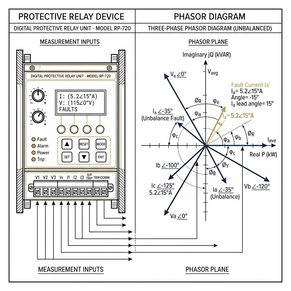
Comparators are the core decision-making elements inside protective relays.
Section 2
Role of Comparators in Protective Relaying
A comparator is a device that compares two electrical quantities
In relays, comparators compare: magnitudes (amplitude) or phase angles (phase)
Output: Binary decision — Operate (Trip) or Restrain
Replaces electromagnetic torque balance in digital/static relays
Two input signals: S₁ (operating) and S₂ (restraining)
Input S₁
Input S₂
COMPARATOR
Trip Signal
Amplitude Comparator
compares |S₁| vs |S₂|
Phase Comparator
compares ∠(S₁ vs S₂)
The comparator defines the operating characteristic (circle, straight line, lens) of the relay on the R-X diagram.
Section 3
Types of Comparators – Overview
AMPLITUDE COMPARATOR
Compares magnitudes of two signals
Operates when |S₁| ≥ |S₂|
Produces circular/offset characteristics
<strong style="color: #c8962b;">Examples:</strong> Overcurrent relay, Impedance relay
<strong style="color: #c8962b;">Also called:</strong> Modulus comparator
PHASE COMPARATOR
Compares phase angles of two signals
Operates when -90° ≤ ∠(S₁,S₂) ≤ +90°
Produces MHO / lens / straight line characteristics
<strong style="font-weight: 800; color: #0a1f4b;">Examples:</strong> Mho relay, Directional relay
<strong style="font-weight: 800; color: #0a1f4b;">Also called:</strong> Cosine / Sine comparator
Any amplitude comparator can be converted to a phase comparator and vice versa — <strong style="color:#c8962b; font-weight: 800;">DUALITY PRINCIPLE</strong>
Section 4
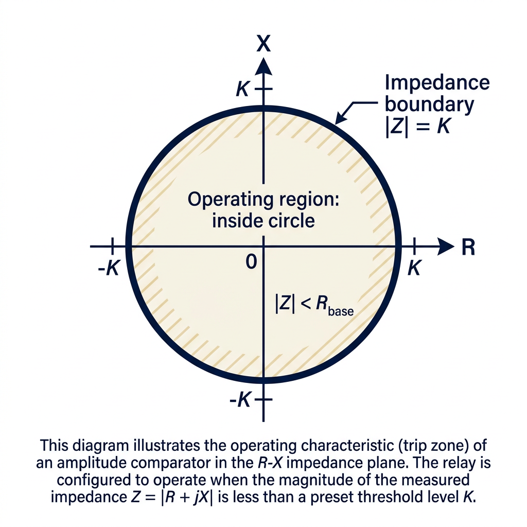
Amplitude Comparator – Concept & Theory
An amplitude comparator compares the magnitudes of two input signals S₁ and S₂ and produces a trip output when the magnitude of S₁ exceeds that of S₂.
Operating signal (function of fault current/voltage)
Restraining signal (reference/threshold)
Section 4
Amplitude Comparator – Mathematical Formulation
Section 5
Amplitude Comparator – Methods of Implementation
Rectifier Bridge Method
Uses rectifier bridges to convert AC signals to DC. Compares DC levels. Simple and robust. Common in electromechanical and early static relays.
Peak Detection / Sampling Method
Samples instantaneous values of S₁ and S₂ at regular intervals. Digital processor compares sampled magnitudes. Used in numerical/digital relays.
RMS Comparison Method
Computes RMS values of S₁ and S₂ over one cycle. Compares RMS: If RMS(S₁) ≥ RMS(S₂) → trip. Most accurate for sinusoidal signals.
Section 5
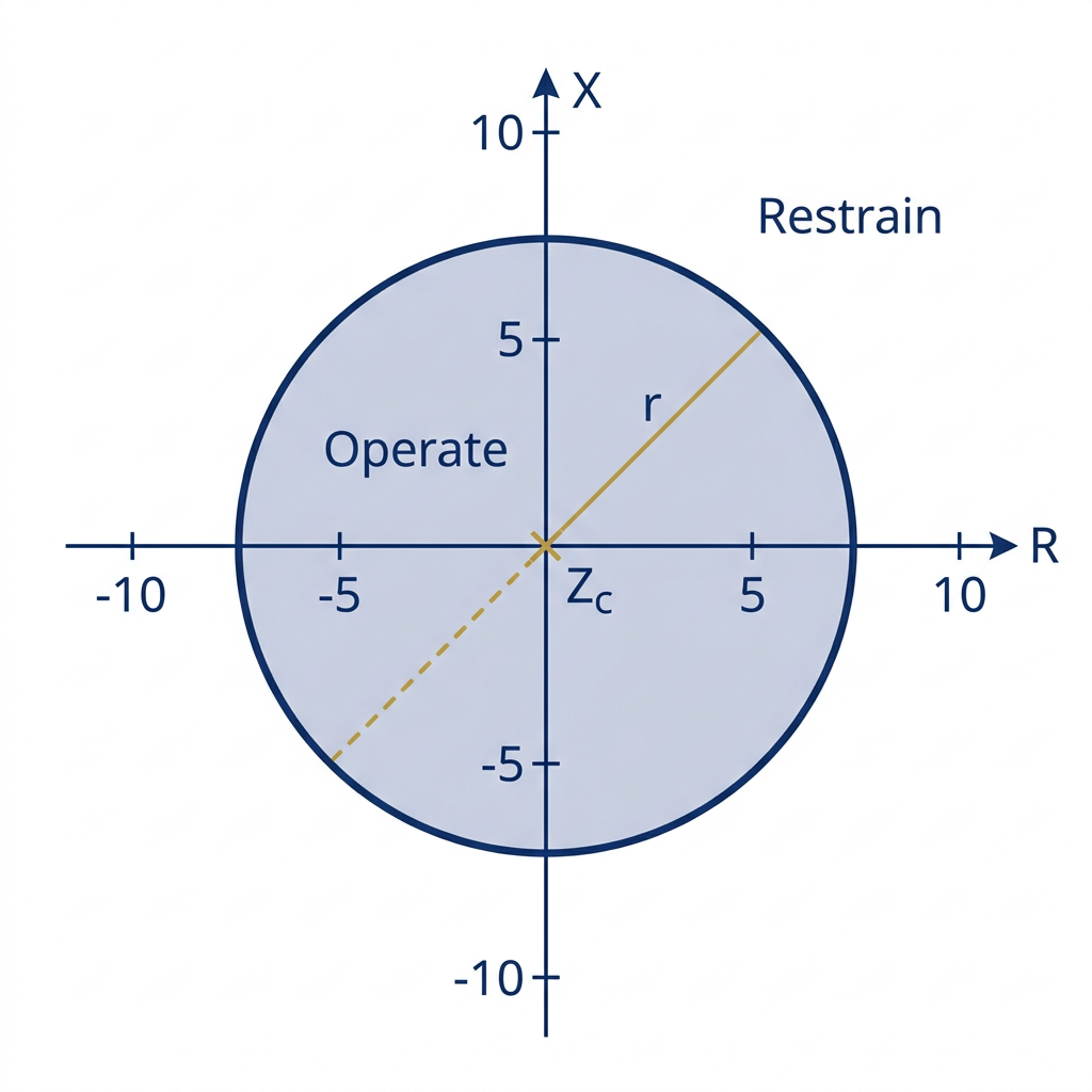
Amplitude Comparator – Characteristics on R-X Plane
Key relay characteristics produced:
Department of Electrical Engineering | Power Systems & Protection
Section 5
Amplitude Comparator – Applications in Relays
01
Overcurrent Relay
Compares fault current |I<sub>fault</sub>| with pickup setting |I<sub>set</sub>|.<br/>Trips when |I<sub>fault</sub>| ≥ |I<sub>set</sub>|.
S<sub>1</sub> = I, S<sub>2</sub> = I<sub>set</sub>
02
Impedance Relay
Compares |V| with |I·Z<sub>set</sub>|.<br/>Trips when |V| ≤ |I·Z<sub>set</sub>|.
S<sub>1</sub> = I·Z<sub>set</sub>, S<sub>2</sub> = V
03
Differential Relay
Compares differential current |I<sub>d</sub>| with restraining current |I<sub>r</sub>|.<br/>Trips when |I<sub>d</sub>| ≥ k·|I<sub>r</sub>|.
S<sub>1</sub> = I<sub>d</sub>, S<sub>2</sub> = k·I<sub>r</sub>
04
Voltage Relay
Compares terminal voltage |V| with reference |V<sub>ref</sub>|.<br/>Trips on under/over voltage.
S<sub>1</sub> = V<sub>ref</sub>, S<sub>2</sub> = V <span style="font-family: 'Segoe UI', Roboto, sans-serif; font-size: 18px; font-weight: 400; color: #666; font-style: normal; margin-left: 10px;">(for undervoltage)</span>
Section 6
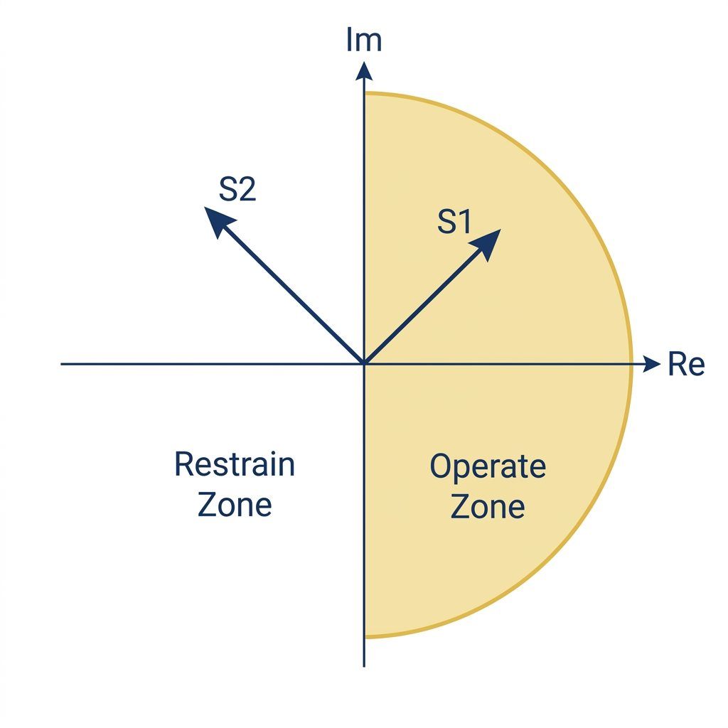
Phase Comparator – Concept & Theory
A phase comparator compares the phase angle between two input signals S₁ and S₂. It produces a trip output when the phase difference falls within a defined range.
Operate if:
−90° ≤ ∠(S₁/S₂) ≤ +90°
i.e., cos∠(S₁, S₂) ≥ 0
Equivalent: Re(S₁ · S₂*) ≥ 0
Where S₂* = complex conjugate of S₂
Cosine Comparator:
operates when cos(θ) ≥ 0 (θ = phase difference)
Sine Comparator:
operates when sin(θ) ≥ 0
Department of Electrical Engineering | Power Systems & Protection
Phase Comparator – Mathematical Formulation
SECTION 6
Department of Electrical Engineering | Power Systems & Protection
<i>S<sub>1</sub> = aV + bI</i>
<i>S<sub>2</sub> = cV + dI</i>
-90° ≤ arg(<i>S<sub>1</sub> / S<sub>2</sub></i>) ≤ 90°
Re(<i>S<sub>1</sub> · S̄<sub>2</sub></i>) ≥ 0
Re[(<i>aZ + b</i>)(<i>c̄Z̄ + d̄</i>)] ≥ 0
This describes a CIRCLE passing through the origin on the R-X plane when appropriate coefficients are chosen.
<i>S<sub>1</sub> = V, S<sub>2</sub> = I · Z<sub>r</sub></i>
-90° ≤ ∠(<i>V / I · Z<sub>r</sub></i>) ≤ 90°
Circle passing through origin with diameter = <i>Z<sub>r</sub></i>
Section 7
Phase Comparator – Methods of Implementation
METHOD 1 – Coincidence Timing Method
Measures the time during which both S₁ and S₂ have the same polarity. If the coincidence time > T/2 (half cycle), the relay operates. Simple and widely used in static relays.
Coincidence time > T/2 → Operate
METHOD 2 – Product (Multiplication) Method
Computes the product S₁ × S₂. If the time-average of the product is positive: ⟨S₁·S₂⟩ > 0 → Trip. Equivalent to checking cos(θ) ≥ 0. Common in analog multiplier circuits.
⟨S₁·S₂⟩ = |S₁||S₂|cosθ ≥ 0 → Operate
METHOD 3 – Digital Phase Angle Measurement
Microprocessor measures the zero-crossing instants of S₁ and S₂. Calculates phase difference θ digitally. Trips if |θ| ≤ 90°. Used in modern numerical relays.
Discrete Fourier Transform (DFT) extracts phase angles
Department of Electrical Engineering | Power Systems & Protection
Section 7
Phase Comparator – Characteristics on R-X Plane
The exact characteristic shape depends on the geometric mapping choices for S₁ and S₂ on the complex impedance plane:
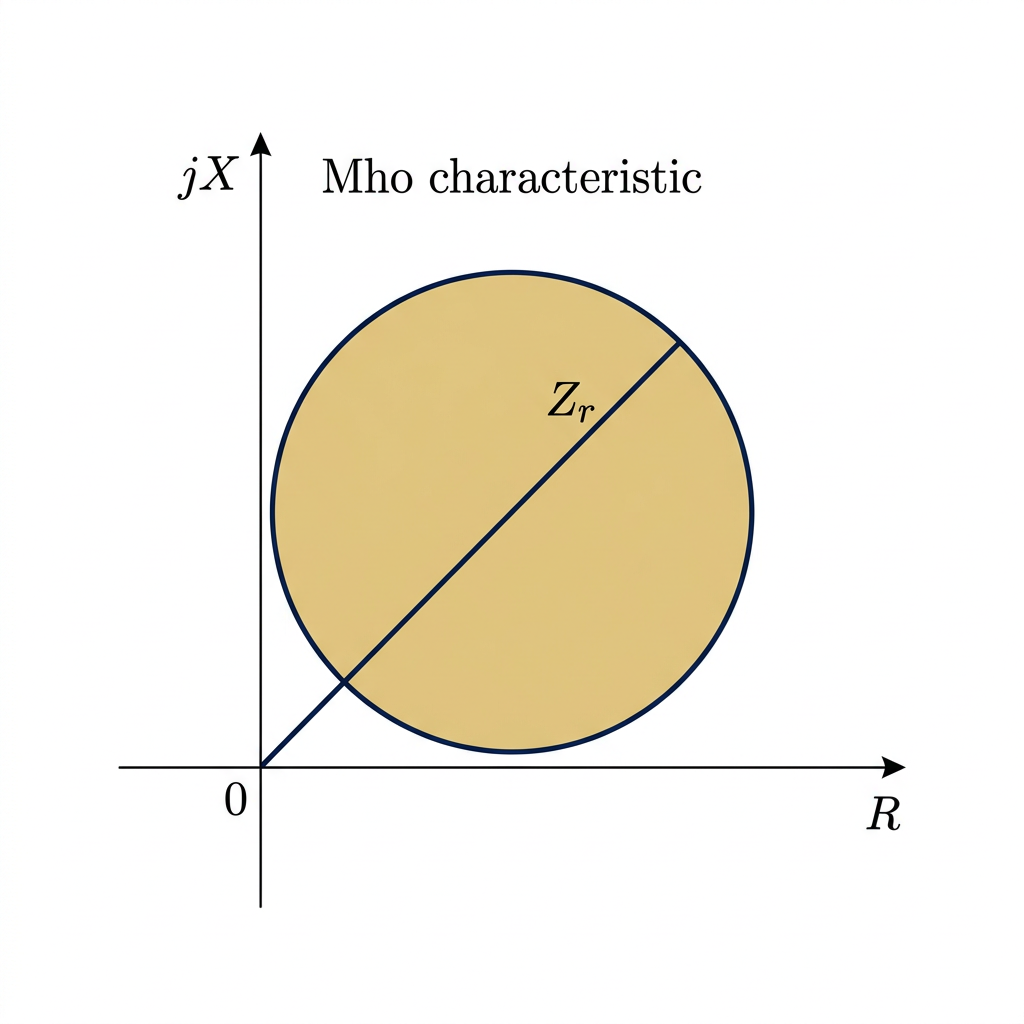
Case 1 — Mho Relay
S₁ = V, S₂ = IZr
<ul style="margin:0; padding-left: 20px; color: #555;"><li style="margin-bottom: 5px;">Circle passing through origin, diameter = Zr</li><li>Self-polarized Mho characteristic</li></ul>
Case 2 — Offset Mho
S₁ = V + IZr, S₂ = V - IZr
<ul style="margin:0; padding-left: 20px; color: #555;"><li>Circle offset from origin framing standard reach</li></ul>
Case 3 — Lens Characteristic
Intersecting Mho Circles
<ul style="margin:0; padding-left: 20px; color: #555;"><li style="margin-bottom: 5px;">Lens-shaped operating zone</li><li>More selective, avoids load encroachment</li></ul>
Case 4 — Straight Line
S₁ = I·Zr, S₂ = V
<ul style="margin:0; padding-left: 20px; color: #555;"><li style="margin-bottom: 5px;">Straight line through origin</li><li>Pure directional element operation</li></ul>
Department of Electrical Engineering | Power Systems & Protection
Section 8
Duality Between Amplitude & Phase Comparators
<strong style="font-weight: 800; letter-spacing: 0.5px;">DUALITY PRINCIPLE:</strong> Any amplitude comparator with inputs <span style="font-family: 'Georgia', serif; font-weight: 700;">(S₁, S₂)</span> is equivalent to a phase comparator with inputs <span style="font-family: 'Georgia', serif; font-weight: 700;">(S₁+S₂, S₁-S₂)</span>, and vice versa.
Amplitude → Phase Conversion
<div style="font-size: 23px; color: #444; line-height: 1.6;"> <div style="display: flex; align-items: baseline; margin-bottom: 16px;"> <div style="width: 8px; height: 8px; background: #c8962b; border-radius: 50%; margin-right: 15px; transform: translateY(-3px); flex-shrink: 0;"></div> <span>Amplitude comparator: <strong style="color: #0a1f4b; font-family: 'Georgia', serif; margin-left: 8px; font-size: 26px;">|S₁| ≥ |S₂|</strong></span> </div> <div style="display: flex; align-items: baseline; margin-bottom: 22px;"> <div style="width: 8px; height: 8px; background: #c8962b; border-radius: 50%; margin-right: 15px; transform: translateY(-3px); flex-shrink: 0;"></div> <span>Define: <strong style="color: #0a1f4b; font-family: 'Georgia', serif; margin-left: 8px; font-size: 26px;">A = S₁ + S₂, B = S₁ - S₂</strong></span> </div> <div style="display: flex; align-items: center; margin-bottom: 22px; padding: 14px 20px; background: rgba(200, 150, 43, 0.1); border-left: 5px solid #c8962b; border-radius: 0 8px 8px 0;"> <span style="font-size: 24px; color: #c8962b; margin-right: 15px; font-weight: bold;">→</span> <span>Equivalent phase comparator:<strong style="color: #0a1f4b; font-family: 'Georgia', serif; margin-left: 12px; font-size: 26px;">-90° ≤ ∠(A,B) ≤ 90°</strong></span> </div> <div style="font-size: 20px; color: #555; font-style: italic; background: rgba(10, 31, 75, 0.04); padding: 12px 20px; border-radius: 6px;"> <strong style="color: #0a1f4b;">Proof note:</strong> |S₁|² ≥ |S₂|² ⇔ Re(S₁·S₂*) ≥ 0 <br> <span style="font-size: 18px; color:#777;">(when |S₁|=|S₂|, on boundary)</span> </div> </div>
Phase → Amplitude Conversion
<div style="font-size: 23px; color: #444; line-height: 1.6;"> <div style="display: flex; align-items: baseline; margin-bottom: 16px;"> <div style="width: 8px; height: 8px; background: #c8962b; border-radius: 50%; margin-right: 15px; transform: translateY(-3px); flex-shrink: 0;"></div> <span>Phase comparator: <strong style="color: #0a1f4b; font-family: 'Georgia', serif; margin-left: 8px; font-size: 26px;">-90° ≤ ∠(S₁,S₂) ≤ 90°</strong></span> </div> <div style="display: flex; align-items: baseline; margin-bottom: 22px;"> <div style="width: 8px; height: 8px; background: #c8962b; border-radius: 50%; margin-right: 15px; transform: translateY(-3px); flex-shrink: 0;"></div> <span>Define: <strong style="color: #0a1f4b; font-family: 'Georgia', serif; margin-left: 8px; font-size: 26px;">P = S₁ + S₂, Q = S₁ - S₂</strong></span> </div> <div style="display: flex; align-items: center; margin-bottom: 22px; padding: 14px 20px; background: rgba(200, 150, 43, 0.1); border-left: 5px solid #c8962b; border-radius: 0 8px 8px 0;"> <span style="font-size: 24px; color: #c8962b; margin-right: 15px; font-weight: bold;">→</span> <span>Equivalent amplitude comparator:<strong style="color: #0a1f4b; font-family: 'Georgia', serif; margin-left: 12px; font-size: 26px;">|P| ≥ |Q|</strong></span> </div> </div>
This duality means the same physical relay hardware can be configured as either type.
Section 9
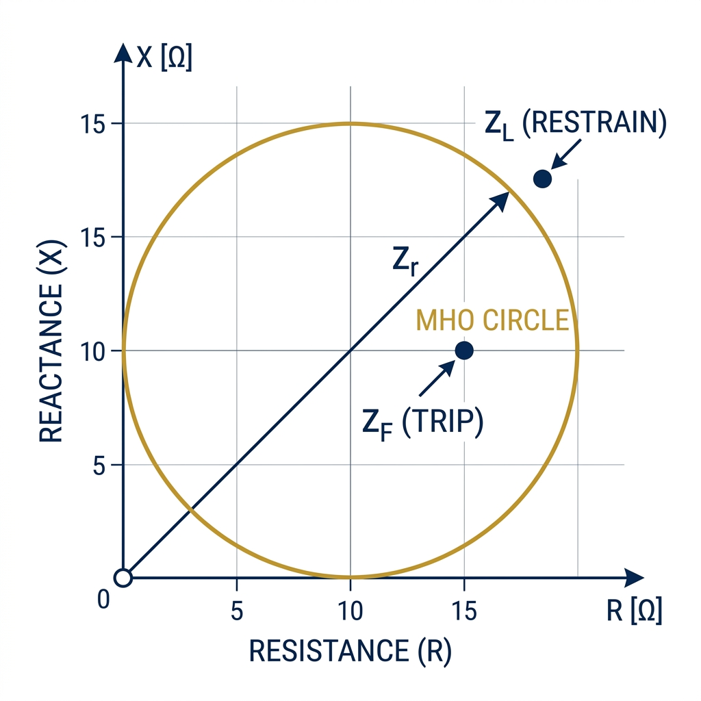
Mho Relay – Phase Comparator Implementation
The Mho relay is the classic implementation of a phase comparator.
Relay Inputs from CT and VT
Voltage: V (from VT at relay location)
Current: I (from CT at relay location)
Comparator Signals
S₁ = V
(operating signal)
S₂ = I × Zr
(polarizing/reference signal, Zr = relay setting impedance)
Operating Condition
-90° ≤ ∠(V, I·Zr) ≤ +90°
→ Equivalent: -90° ≤ (∠Z - ∠Zr) ≤ +90°
→ The measured impedance Z lies within the Mho circle
The Mho Circle
Passes through the origin (R-X plane)
Diameter = |Zr| at angle ∠Zr
Self-polarized (uses its own voltage)
Department of Electrical Engineering | Power Systems & Protection
Section 9
Directional Relay – Phase Comparator Application
Department of Electrical Engineering | Power Systems & Protection
Section 9
Distance Protection Using Comparator Techniques
Distance relays protect transmission lines by continuously measuring impedance <b style="color: #0a1f4b; font-size: 27px;">Z = V/I</b>. A fault immediately creates a dangerously low impedance value that actively falls <b style="color: #c8962b;">inside the predefined relay characteristic</b>.
<svg width="680" height="680" viewBox="0 0 700 700" xmlns="http://www.w3.org/2000/svg" style="border-radius:12px; font-family:'Segoe UI', sans-serif;"> <defs> <marker id="arrowHead" markerWidth="6" markerHeight="6" refX="5" refY="3" orient="auto"> <path d="M0,0 L0,6 L6,3 z" fill="#333" /> </marker> </defs> <!-- Faint Grid for visual context --> <g stroke="rgba(0,0,0,0.03)" stroke-width="1.5"> <line x1="200" y1="120" x2="680" y2="120"/> <line x1="200" y1="220" x2="680" y2="220"/> <line x1="200" y1="320" x2="680" y2="320"/> <line x1="200" y1="420" x2="680" y2="420"/> <line x1="300" y1="50" x2="300" y2="520"/> <line x1="400" y1="50" x2="400" y2="520"/> <line x1="500" y1="50" x2="500" y2="520"/> <line x1="600" y1="50" x2="600" y2="520"/> </g> <!-- X-axis (R) --> <line x1="80" y1="520" x2="650" y2="520" stroke="#333" stroke-width="2.5" marker-end="url(#arrowHead)" /> <text x="640" y="555" fill="#222" font-size="22" font-weight="bold" font-style="italic">R</text> <!-- Y-axis (jX) --> <line x1="200" y1="620" x2="200" y2="50" stroke="#333" stroke-width="2.5" marker-end="url(#arrowHead)" /> <text x="160" y="65" fill="#222" font-size="22" font-weight="bold" font-style="italic">jX</text> <!-- Origin point --> <text x="175" y="545" fill="#222" font-size="22" font-weight="bold">O</text> <!-- Line Impedance Characteristic (Angle = 60 deg) --> <line x1="200" y1="520" x2="490" y2="17.72" stroke="#444" stroke-width="3" stroke-dasharray="6,4" /> <text x="390" y="165" fill="#444" font-size="20" font-weight="700" transform="rotate(-60 390 165)">Line Characteristic Z_L</text> <!-- Center and Circle Formulas: Angle=60, Origin=(200, 520) Cx = 200 + R*0.5 Cy = 520 - R*0.86602 --> <!-- Zone 3 Circle (Radius 265) --> <circle cx="332.5" cy="290.5" r="265" fill="rgba(136,136,136,0.02)" stroke="#888888" stroke-width="3" stroke-dasharray="14,10" /> <text x="605" y="295" fill="#888888" font-size="22" font-weight="bold">Zone 3</text> <!-- Zone 2 Circle (Radius 150) --> <circle cx="275" cy="390.1" r="150" fill="rgba(200,150,43,0.03)" stroke="#c8962b" stroke-width="4.5" stroke-dasharray="12,8" /> <text x="440" y="445" fill="#c8962b" font-size="22" font-weight="bold">Zone 2</text> <!-- Zone 1 Circle (Radius 100) --> <circle cx="250" cy="433.4" r="100" fill="rgba(10,31,75,0.08)" stroke="#0a1f4b" stroke-width="4" /> <text x="325" y="510" fill="#0a1f4b" font-size="22" font-weight="bold">Zone 1</text> <!-- Fault Point Z_F (Inside Zone 1, dist 120 along line -> X=260, Y=416) --> <circle cx="260" cy="416" r="8" fill="#e53935" stroke="#fff" stroke-width="2.5" /> <text x="275" y="415" fill="#e53935" font-size="22" font-weight="bold">Z_F (Fault)</text> <!-- Marker for Origin to Z_F --> <line x1="200" y1="520" x2="260" y2="416" stroke="#e53935" stroke-width="4" /> <!-- Load Region (Bottom Right Quadrant representation) --> <path d="M 400 450 Q 550 420 620 450 Q 640 500 500 500 Q 400 480 400 450 Z" fill="rgba(10,31,75,0.05)" stroke="#0a1f4b" stroke-width="2" stroke-dasharray="6,6" /> <text x="460" y="475" fill="#0a1f4b" font-size="20" font-weight="bold">Load Region</text> </svg>
Section 10
Comparator Realization in Static Relays
Static Amplitude Comparator
Uses operational amplifiers (op-amps) and rectifier circuits.
S₁ → [Rectifier] → |S₁| ─┐ ├→ [Diff. Amp] → [Level Detector] → Trip S₂ → [Rectifier] → |S₂| ─┘
<div style="display: flex; flex-direction: column; gap: 14px;"><div style="display: flex; align-items: flex-start;"><span style="color: #c8962b; margin-right: 15px; font-weight: bold; font-size: 26px; line-height: 22px;">•</span><div>Full-wave bridge rectifiers</div></div><div style="display: flex; align-items: flex-start;"><span style="color: #c8962b; margin-right: 15px; font-weight: bold; font-size: 26px; line-height: 22px;">•</span><div>Differential op-amp</div></div><div style="display: flex; align-items: flex-start;"><span style="color: #c8962b; margin-right: 15px; font-weight: bold; font-size: 26px; line-height: 22px;">•</span><div>Schmitt trigger for clean switching</div></div><div style="display: flex; align-items: flex-start;"><span style="color: #c8962b; margin-right: 15px; font-weight: bold; font-size: 26px; line-height: 22px;">•</span><div>Output relay or thyristor</div></div></div>
Static Phase Comparator (Coincidence Type)
Detects overlapping positive half-cycles of S₁ and S₂.
S₁ → [Zero-Crossing Detector] ─┐ ├→ [AND Gate] → [Timer] → Trip S₂ → [Zero-Crossing Detector] ─┘
<div style="display: flex; flex-direction: column; gap: 14px;"><div style="display: flex; align-items: flex-start;"><span style="color: #c8962b; margin-right: 15px; font-weight: bold; font-size: 26px; line-height: 22px;">•</span><div>Zero-crossing detectors</div></div><div style="display: flex; align-items: flex-start;"><span style="color: #c8962b; margin-right: 15px; font-weight: bold; font-size: 26px; line-height: 22px;">•</span><div>AND logic gate</div></div><div style="display: flex; align-items: flex-start;"><span style="color: #c8962b; margin-right: 15px; font-weight: bold; font-size: 26px; line-height: 22px;">•</span><div>Monostable timer (measures coincidence period)</div></div><div style="display: flex; align-items: flex-start;"><span style="color: #c8962b; margin-right: 15px; font-weight: bold; font-size: 26px; line-height: 22px;">•</span><div>Output: Trip if coincidence > T/2</div></div></div>
Static relays replaced electromagnetic relays in 1970s–1980s, offering faster response and improved accuracy.
Section 10
Comparator Implementation in Numerical (Digital) Relays
CT / VT
Analog Filter
A/D Converter
DSP / Microprocessor
Comparator Algorithm
Trip Logic
Amplitude Comparator in Numerical Relay
Computes phasor magnitudes using <b style="color: #0a1f4b;">DFT</b> (Discrete Fourier Transform)
<span style="color: #0a1f4b; font-size: 28px; font-family: monospace;"><b>|S₁|²</b> = (Re_S₁)² + (Im_S₁)²</span>
Compare: if <span style="color: #0a1f4b; font-size: 28px; font-family: monospace;"><b>|S₁| ≥ |S₂|</b></span> → set Trip flag
Updated every half-cycle or per-sample
Phase Comparator in Numerical Relay
Computes phasors <b style="color: #0a1f4b;">S₁</b> and <b style="color: #0a1f4b;">S₂</b> via DFT
Phase angle:<br/><span style="color: #0a1f4b; font-size: 28px; font-family: monospace;"><b>θ</b> = arg(S₁) − arg(S₂) = arctan(Im/Re)</span>
Or: uses dot product:<br/><span style="color: #0a1f4b; font-size: 28px; font-family: monospace;"><b>Re(S₁·S₂*) ≥ 0</b></span> → Trip
Updated every sample interval (e.g., every 1ms)
Numerical relays sample at 1–4 kHz, process signals digitally, and implement multiple relay functions (overcurrent, distance, differential) simultaneously in software.
Summary
Amplitude vs Phase Comparators – Comparative Analysis
Feature
Amplitude Comparator
Phase Comparator
Operating Criterion
|S₁| ≥ |S₂|
-90° ≤ ∠(S₁,S₂) ≤ +90°
R-X Characteristic
Circle (any position)
Circle through origin / Lens
Typical Relay Type
Impedance, Overcurrent, Differential
Mho, Directional, Distance
Implementation
Rectifier bridge, RMS comparison
Coincidence, Product, Phase angle
Effect of Arc Resistance
Less affected
More affected (circle through origin)
Load Encroachment
Higher risk
Lower risk (Mho is more directional)
Polarization Needed
Not required
Required for directional characteristic
Duality
Can be converted to phase comparator
Can be converted to amplitude comparator
Use in Modern Relays
Yes (digital implementation)
Yes (preferred for distance protection)
Department of Electrical Engineering | Power Systems & Protection
Section 10
Practical Considerations & Limitations
Design Considerations
CT/VT accuracy directly affects comparator inputs — must use class PS/X CTs
Signal filtering needed to remove harmonics before comparison
DC offset in fault current can cause errors — mitigated by Fourier filtering
For phase comparators: polarization source must remain stable during faults
Memory voltage polarization used when VT voltage collapses during close-in faults
Temperature drift in analog circuits must be compensated
Limitations
Amplitude comparators: susceptible to arc resistance (inflates impedance)
Phase comparators (Mho): reduced reach for high resistance faults
Load encroachment can cause incorrect operation during heavy load
Mutual coupling on parallel lines can cause errors in phase measurement
Instrument transformer errors introduce measurement inaccuracies
Saturation of CTs during heavy faults can corrupt comparator inputs
Modern numerical relays use adaptive algorithms and multiple comparators in parallel zones to overcome these limitations.
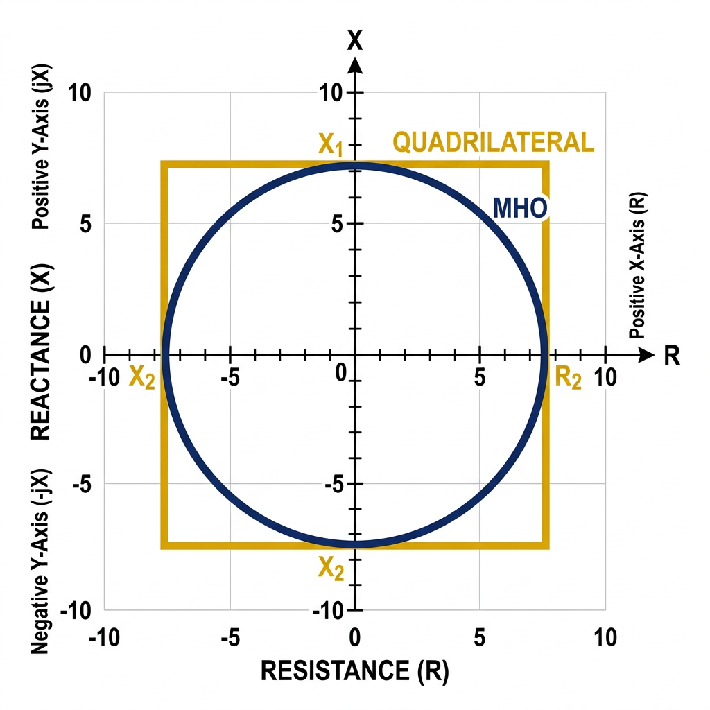
ADVANCED TOPICS
Advanced Topics: Quadrilateral Characteristic & Adaptive Relaying
Quadrilateral Characteristic
Adaptive Relaying
Department of Electrical Engineering | Power Systems & Protection
Conclusion
Summary & Conclusion
Comparator Fundamentals
Comparators are the decision core of protective relays, comparing either amplitudes or phase angles of two derived signals to produce trip/restrain outputs.
Amplitude Comparators
Operate when |S₁| ≥ |S₂|. Produce circular characteristics on R-X plane. Implemented via rectifier bridges or digital RMS comparison. Used in: Overcurrent, Impedance, Differential relays.
Phase Comparators
Operate when phase difference is within ±90°. Produce Mho/lens characteristics. Implemented via coincidence timing or digital DFT. Used in: Mho relay, Directional relay, Distance protection.
Duality Principle
Any amplitude comparator ↔ phase comparator conversion is possible. Inputs transform as: (S₁,S₂) ↔ (S₁+S₂, S₁-S₂). This unifies relay theory.
Modern numerical relays implement both comparator types digitally using DFT-based phasor estimation, offering flexibility, precision, and multiple protection functions in one device.
References: Phadke & Thorp – Computer Relaying | Blackburn – Protective Relaying | Anderson – Power System Protection
- protective-relays
- electrical-engineering
- power-systems
- mho-relay
- distance-protection
- amplitude-comparator
- phase-comparator
- static-relays