Experimental Determination of Moment of Inertia on Incline
Learn how to calculate and compare the Moment of Inertia for cylinders and spheres using an inclined plane experiment and energy conservation formulas.
Determination of Moment of Inertia
Experimental Analysis of Solid Cylinders, Hollow Cylinders, and Spheres
Objective
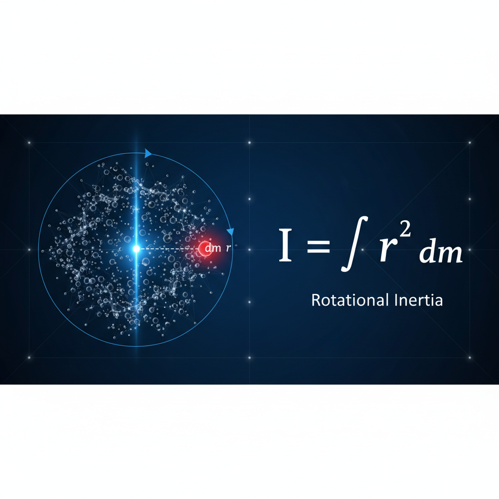
This experiment aims to experimentally determine the Moment of Inertia (I) of various rigid bodies: a solid cylinder, a hollow cylinder, and a solid sphere. <br><br><b>Key Concepts:</b><br>• Moment of Inertia is the rotational analog of mass.<br>• It relies on the distribution of mass relative to the axis of rotation.<br>• We will verify theoretical predictions by observing the dynamics of these objects rolling down an inclined plane.
Apparatus Required
<ul><li><b>Inclined Plane:</b> Adjustable angle rigid board.</li><li><b>Test Objects:</b> Solid cylinder, Hollow cylinder (pipe), Solid sphere.</li><li><b>Measurement Tools:</b> Vernier calipers (for radius), Electronic Balance (for mass).</li><li><b>Timing:</b> Digital stopwatch or photogate sensors.</li><li><b>Others:</b> Meter scale, Soft stopping barrier, Spirit level.</li></ul>
Theory: Conservation of Energy
When a rigid body rolls down a frictionless incline without slipping, its potential energy is converted into both translational and rotational kinetic energy.<br><br><b>Equation:</b><br>mgh = ½mv² + ½Iω²<br><br><b>Where:</b><br>• v = velocity of center of mass<br>• ω = angular velocity (v = Rω for pure rolling)<br>• h = vertical height<br>• I = Moment of Inertia about center of mass
Theoretical Formulas for Objects
The geometric distribution of mass determines the specific formula for 'I':
<div style='text-align:center; padding:20px; background:white; border-radius:8px; box-shadow:0 4px 10px rgba(0,0,0,0.1);'><h3 style='color:#003366;'>Solid Cylinder</h3><p style='font-size:32px; font-weight:bold;'>I = ½ MR²</p><p style='font-size:18px; color:#666;'>Mass distributed throughout</p></div>
<div style='text-align:center; padding:20px; background:white; border-radius:8px; box-shadow:0 4px 10px rgba(0,0,0,0.1);'><h3 style='color:#003366;'>Hollow Cylinder</h3><p style='font-size:32px; font-weight:bold;'>I ≈ MR²</p><p style='font-size:18px; color:#666;'>Mass concentrated at rim<br>(Thin Shell)</p></div>
<div style='text-align:center; padding:20px; background:white; border-radius:8px; box-shadow:0 4px 10px rgba(0,0,0,0.1);'><h3 style='color:#003366;'>Solid Sphere</h3><p style='font-size:32px; font-weight:bold;'>I = ⅖ MR²</p><p style='font-size:18px; color:#666;'>Mass concentrated near center</p></div>
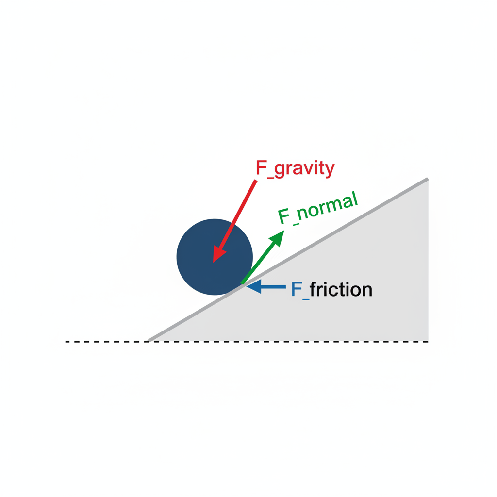
Diagram: Forces on an Incline
<b>Free Body Diagram Analysis:</b><br><br>• <b>mg sin(θ):</b> Component of gravity causing acceleration down the slope.<br>• <b>mg cos(θ):</b> Component balanced by the Normal force (N).<br>• <b>Friction (f):</b> Acts up the slope. Essential for producing the torque (τ = fR) required for rotation.<br>• Without friction, the object would slide, not roll.
Procedure
<ol><li>Measure the mass (M) using a balance and the diameter (2R) using Vernier calipers for all objects.</li><li>Set the inclined plane to a fixed angle (θ) and measure the rollout distance (s).</li><li>Release the object from rest at the top mark. <b>Do not push.</b></li><li>Record the time (t) taken to reach the bottom using a stopwatch.</li><li>Repeat the timing 3-5 times for each object to reduce random error.</li><li>Repeat the experiment for the other geometric shapes.</li></ol>
Calculation Methodology
To find 'I' experimentally, we first find the linear acceleration 'a'.<br><br><b>Step 1: Kinematics</b><br>From s = ut + ½at² (where u=0):<br><span style='font-size:32px; color:#003366; font-weight:bold;'>a = 2s / t²</span><br><br><b>Step 2: Dynamics Equation</b><br>The acceleration of a rolling body is given by:<br><span style='font-size:32px; color:#003366; font-weight:bold;'>a = g sin(θ) / (1 + I/MR²)</span><br><br><b>Step 3: Solve for I</b><br>Rearranging the above gives the experimental Inertia.
Results Summary
Comparison of Theoretical vs. Experimental Moment of Inertia for objects of Mass=1kg, Radius=0.1m.
Discussion of Results
<ul><li><b>Speed Comparison:</b> The sphere reached the bottom fastest, followed by the solid cylinder, then the hollow cylinder. This confirms that higher 'I' results in lower acceleration.</li><li><b>Shape Factor:</b> Although masses were similar, the hollow cylinder had the highest 'I' because its mass is concentrated furthest from the axis (at the rim).</li><li><b>Error Analysis:</b> Experimental values are slightly higher than theoretical.<ul><li><i>Cause 1:</i> Micro-slippage (energy lost to non-conservative work).</li><li><i>Cause 2:</i> Air resistance and friction at the edges.</li><li><i>Cause 3:</i> Objects are not perfectly rigid.</li></ul></li></ul>
Conclusion
The experiment successfully determined the moments of inertia for the test bodies. We concluded that:<br><br>1. <b>Mass Distribution Matters:</b> Inertia depends heavily on how mass is distributed relative to the axis, not just the total mass.<br>2. <b>Geometric Verification:</b> The experimental ordering (Sphere < Solid Cyl < Hollow Cyl) aligns with derived geometric formulas.<br>3. <b>Energy Conservation:</b> The translational-rotational energy transfer model effectively predicts motion on an incline.
- physics-experiment
- moment-of-inertia
- rotational-dynamics
- classical-mechanics
- inclined-plane
- science-lab
- conservation-of-energy