
PWM Signal Generation for EV Motor Control & VCU Drive
Explore PWM techniques for EV motor control, featuring SVPWM, VCU architecture, and 3-phase inverter design for BLDC/PMSM systems by Dataic Motor Systems.
PWM Signal Generation for EV Motor Control
Pulse Width Modulation via VCU for Dataic BLDC/PMSM Motor
Vehicle Control Unit — Motor Drive System
Engineering Technical Presentation | 2026
Dataic Motor Systems | PWM Drive Control
Table of Contents
Introduction to PWM
VCU Architecture
Dataic Motor Overview
PWM Signal Parameters
VCU-to-Motor Interface
PWM Generation Techniques
Space Vector PWM (SVPWM)
Dead-Time & Protection
Firmware Implementation
3-Phase Inverter Circuit
PWM Waveforms & Graphs
System Testing & Validation
Dataic Motor Systems | PWM Drive Control
Performance Results
Conclusion
References & Thank You
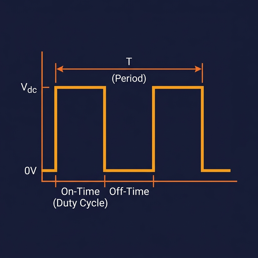
Introduction to Pulse Width Modulation
A technique where the width of pulses in a signal is modulated to control power delivery to a load.
Switching frequency controls motor noise & efficiency
Duty cycle (0–100%) determines average voltage
Used in motor drives, inverters, and power converters.
Duty Cycle = (t_on / T) × 100%
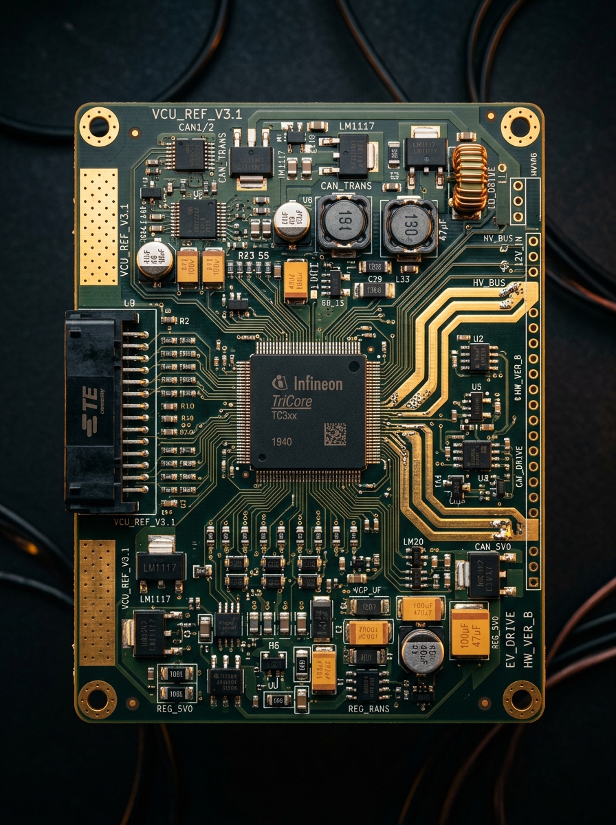
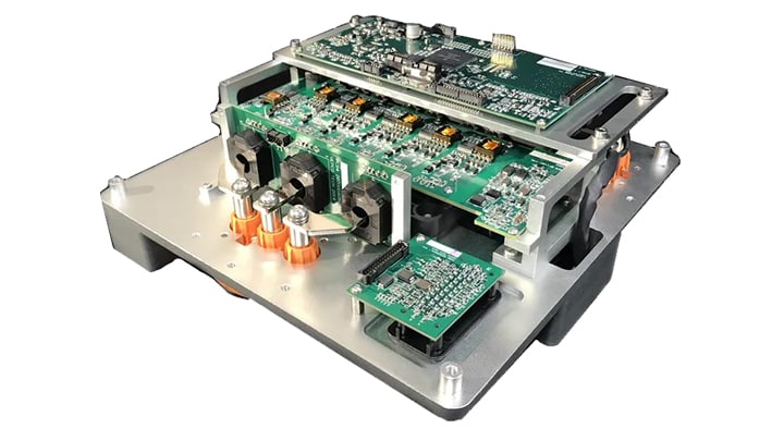
VCU Architecture Overview
Throttle / Pedal
CAN Bus
Battery Mgt System<br>(BMS)
Vehicle Control Unit<br>(VCU)
Motor Inverter /<br>Gate Driver
PWM Signals
Microcontroller:
ARM Cortex-M4/M7
PWM Channels:
6 (3-phase complementary)
Switching Frequency:
8–20 kHz
Vehicle Control Systems | Hardware Architecture
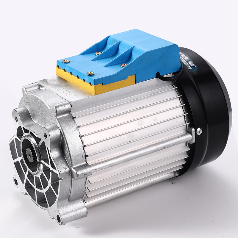
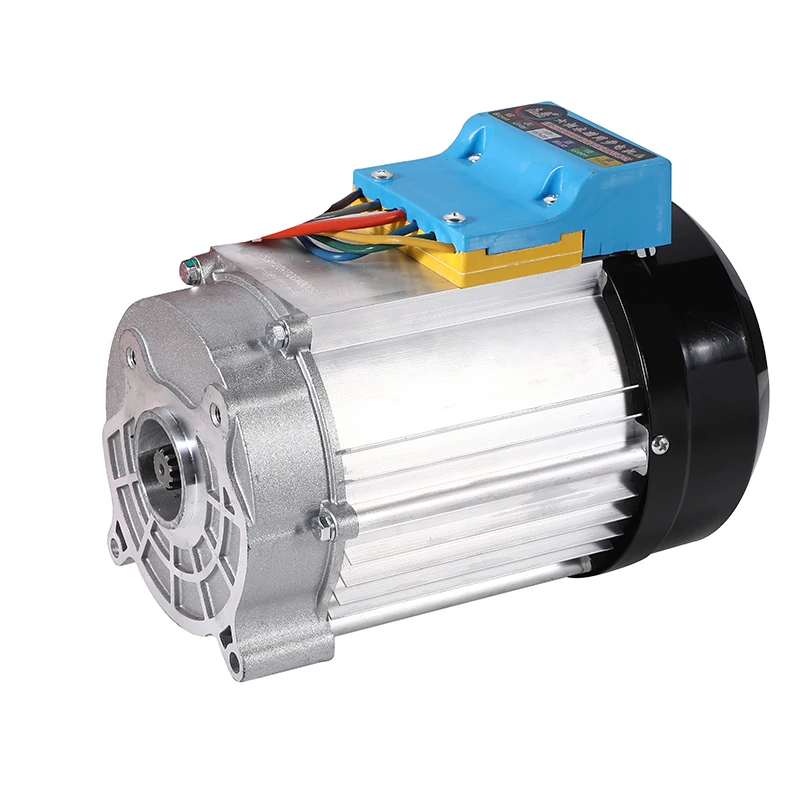
Dataic Motor — Technical Overview
Motor Type
BLDC / PMSM
Power Range
1000W – 8000W
Voltage
48V / 60V / 72V
Phases
3-Phase (or 6-Phase)
Rated Speed
2500–4500 RPM
Peak Torque
Up to 80 Nm
Cooling
Air-cooled
Encoder
Hall sensor / Resolver
Dataic Motor Systems
PWM Signal Parameters & Configuration
FREQUENCY
8–20 kHz typical for EV motors. Higher freq = smoother torque, more switching losses.
DUTY CYCLE
0% = Motor off, 100% = Full voltage. Controlled by VCU torque demand algorithm.
DEAD TIME
2–5 µs inserted between high/low side switching to prevent shoot-through in the inverter bridge.
DEAD-TIME GAP (2–5 µs)
Dataic Motor Systems | Embedded Control Engineering
VCU to Motor Interface — Signal Path
Automotive Propulsion: End-to-End Signal Chain and Power Electronics Architecture
Driver Input / Throttle
VCU (MCU Core)
PWM Output Pins
Gate Driver IC
3-Phase IGBT/MOSFET Inverter
Dataic PMSM Motor
Torque Command
6x PWM signals
Gate Signals (with isolation)
3-Phase AC voltage
Mechanical output
Isolation
Optocoupler/Digital isolator
Gate drive voltage
15V / -5V
Signal logic
3.3V or 5V TTL
Dataic Motor Systems | Electronics Engineering | Hardware Design
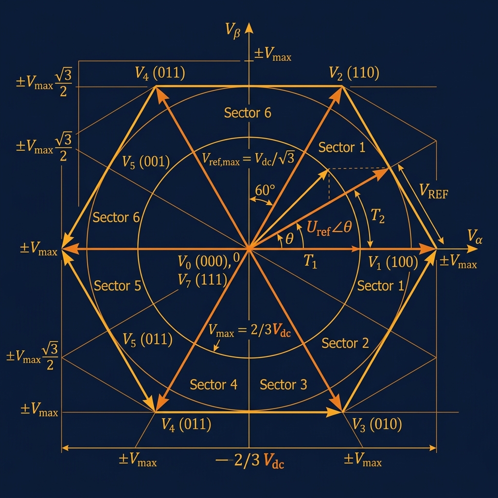
Space Vector PWM (SVPWM)
SVPWM is the most efficient PWM technique for 3-phase motor drives. It maximizes DC bus utilization (up to 15% more than SPWM) and reduces harmonic distortion.
Vehicle Control Unit — Motor Drive System
Engineering Technical Presentation | 2026
Dataic Motor Systems | Space Vector Modulation
Dead-Time Insertion & Protection
Dead-time is a mandatory delay between turning OFF one switch and turning ON the complementary switch in the same inverter leg, preventing a DC bus short-circuit (shoot-through).
Hardware Protection Features
Over-Current
Hardware overcurrent latch via comparator
Over-Temperature
NTC thermistor on IGBT heatsink
Under-Voltage
UVLO disables PWM below safe bus voltage
Dataic Motor Systems | Inverter Protection
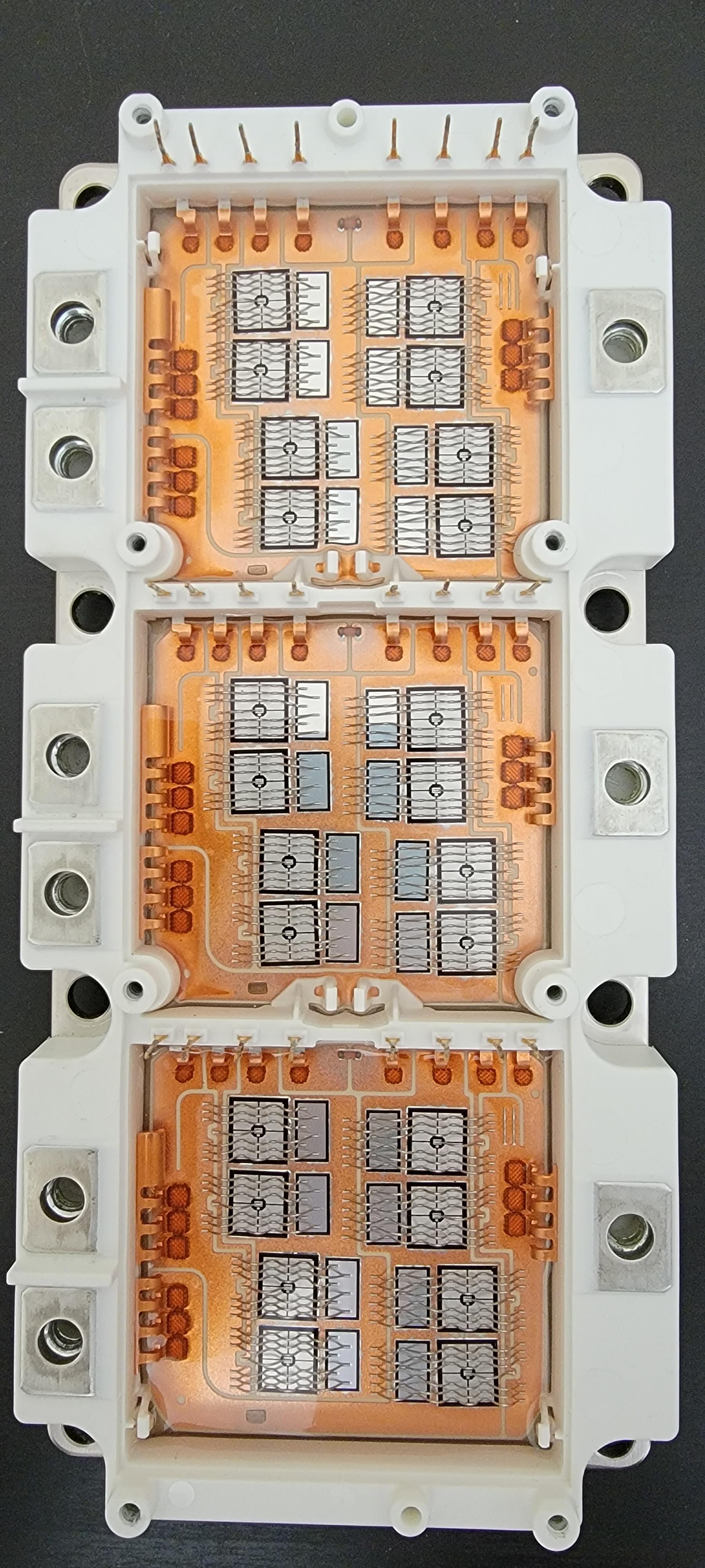
Three-Phase Inverter Circuit Diagram
Circuit Highlights
DC Bus Voltage
400V DC
IGBT Type
SiC MOSFET / IGBT Module
Switching Frequency
10–20 kHz
Gate Drive Voltage
+15V / -5V
Dataic Motor Systems | Power Electronics — Inverter Circuit
PWM Waveforms & Motor Performance Graphs
Measured signal waveforms and motor performance characteristics
PWM Duty Cycle Waveform
Motor Speed vs Duty Cycle
Torque vs Speed Characteristic
Peak Torque:
120 Nm
Max Speed:
4000 RPM
Efficiency:
>94%
Dataic Motor Systems | Waveform Analysis & Performance Data
Firmware Implementation in VCU
Timer peripheral configured in center-aligned mode
Interrupts triggered at PWM period center for ADC sync
FOC loop runs at same rate as PWM (16 kHz)
CAN commands decoded to torque reference in real-time
ARM Cortex-M7 / STM32 Microcontroller
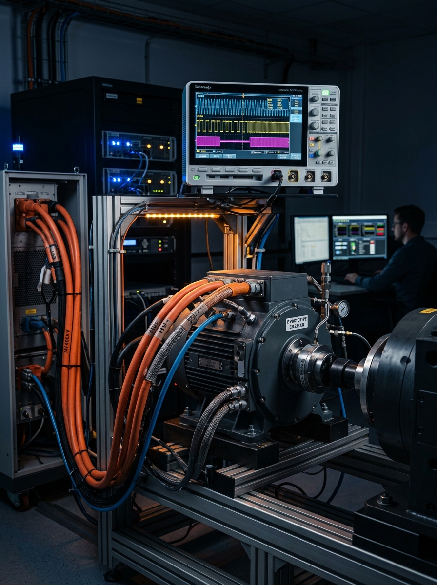
System Testing & Validation
PWM Waveform Test
Verified 16 kHz frequency and variable duty cycle (10%–90%) on oscilloscope. Rise/fall time < 200 ns.
Dead-time Verification
Dead-time gap of 3.5 µs confirmed on all 6 channels. No shoot-through events detected.
Motor Response Test
Smooth torque ramp from 0–80 Nm achieved. Speed control accuracy ±15 RPM at steady state.
All tests conducted at 72V / 5000W motor configuration
Performance Results
DC Bus Utilization
Current THD
Torque Ripple %
75.0%
86.6%
8.2%
5.1%
4.5%
2.8%
16 kHz
PWM Frequency
86.6%
DC Bus Utilization
< 5%
Current THD
Conclusion
PWM via VCU enables precise torque and speed control of Dataic PMSM motors
SVPWM provides superior DC bus utilization and reduced harmonic distortion
Dead-time insertion is critical to prevent inverter shoot-through
Firmware on ARM Cortex-M7 runs FOC loop synchronized with 16 kHz PWM
System validated through oscilloscope, load, and torque response tests
Thank You
Questions & Contact: engineering@dataic.com
Dataic Motor Systems | PWM Drive Control | 2026
- ev-motor-control
- pwm-generation
- vcu-architecture
- bldc-motor
- svpwm
- power-electronics
- inverter-circuit
- embedded-systems