Electronics Basics: Sensors, Inputs, and Outputs Guide
Learn electronics essentials: the difference between analog and digital sensors, using microcontrollers, transistors for high power, and PWM for motion.
Basics of Electronics: Sensors & I/O
Understanding Inputs, Outputs, and Digital vs. Analog
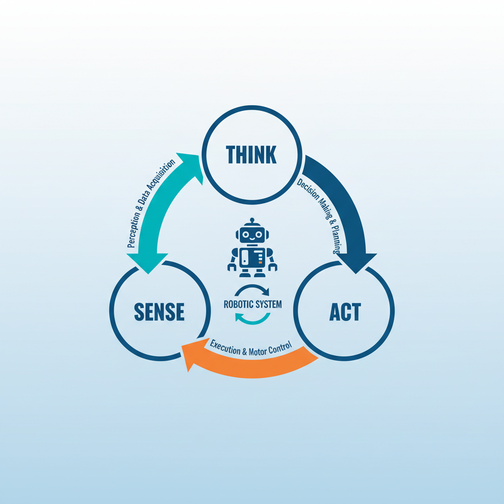
The Big Picture: Sense, Think, Act
SENSE (Input): Gathering data from the physical world.
THINK (Process): The microcontroller decides what to do based on logic.
ACT (Output): Changing the physical world (motion, light, sound).
Defining Inputs & Outputs
INPUTS: Signals sent TO the brain (Microcontroller). They measure the environment.
OUTPUTS: Signals sent FROM the brain. They perform actions or display information.
Analog vs. Digital Signals
Digital is ON/OFF (1 or 0). Analog is continuous (range of values).
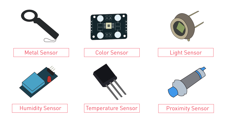
Digital Sensors: The Simplest Inputs
Reports only two states: HIGH (5V) or LOW (0V).
Examples: Push Buttons, Switches, Reed Switches (Magnetic).
Often requires a 'Pull-up' or 'Pull-down' resistor to ensure a clean signal.
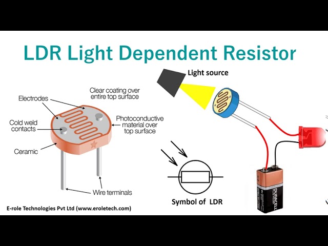
Analog Sensors: Measuring the World
Analog sensors change their RESISTANCE based on the environment. We use a Voltage Divider circuit to read this change as Voltage.
LDR (Light Dependent Resistor): Measures brightness.
Thermistor: Measures temperature.
Potentiometer: Measures rotation (knob).
ADC: Analog to Digital Converter
Microcontrollers are digital (Brain). They don't understand 2.5V. They understand discrete numbers. An ADC translates voltage (0-5V) into a number (e.g., 0-1023).
Basic Outputs: LEDs & Current
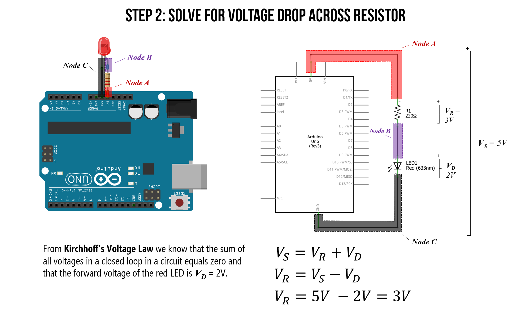
An LED (Light Emitting Diode) is the 'Hello World' of electronics.
SAFETY: LEDs have no internal resistance. You MUST use a resistor to limit current.
Control: Write HIGH (5V) to turn on, LOW (0V) to turn off.
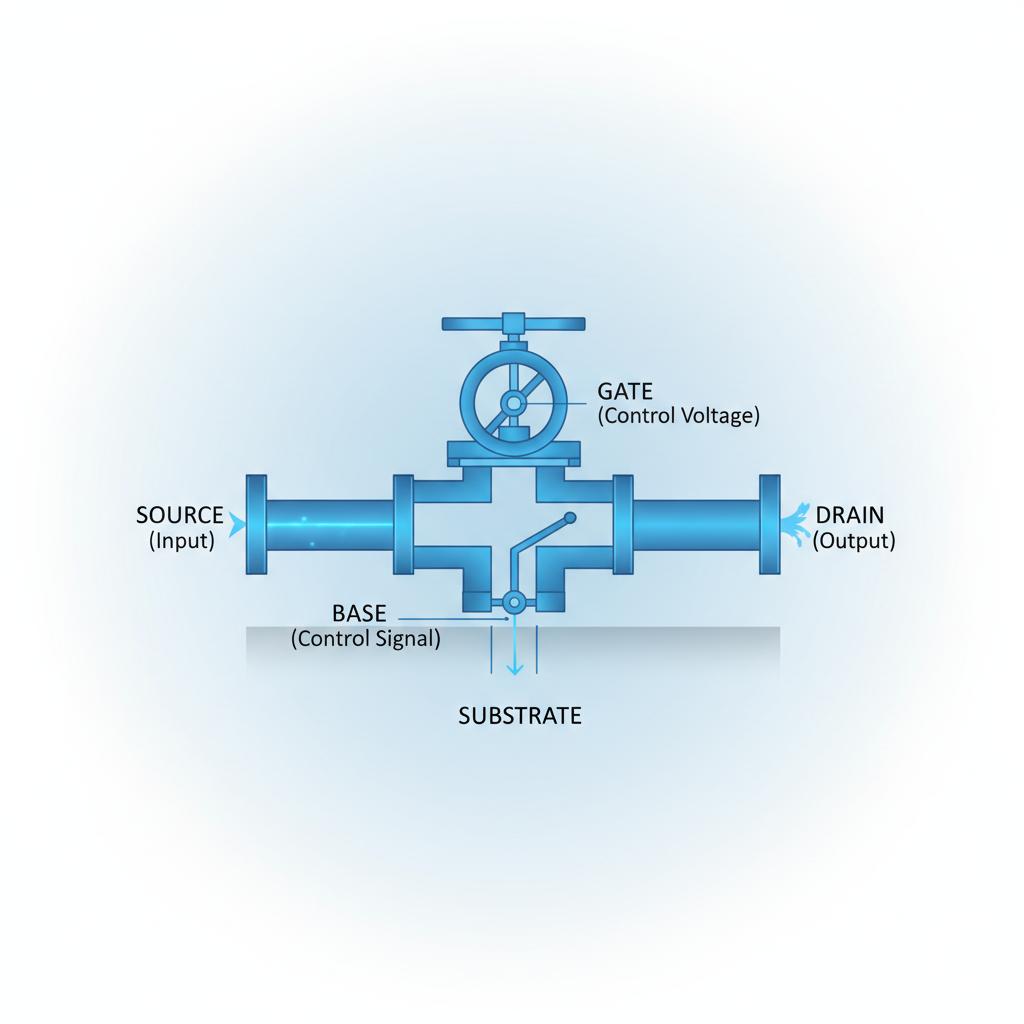
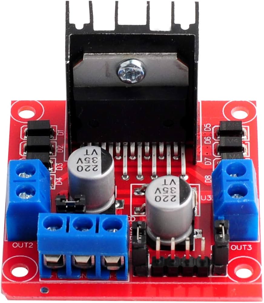
High Power Outputs: Transistors
Problem: Microcontrollers are weak. They can only provide ~20-40mA of current. Motors need 500mA+.
Solution: Use a Transistor (or MOSFET). It acts like a digital switch. A tiny signal from the chip controls massive power from a battery.
Analog Outputs? Meet PWM
Digital pins can't output varying voltage (like 2.5V). Instead, we turn the pin ON and OFF very fast. This is Pulse Width Modulation.
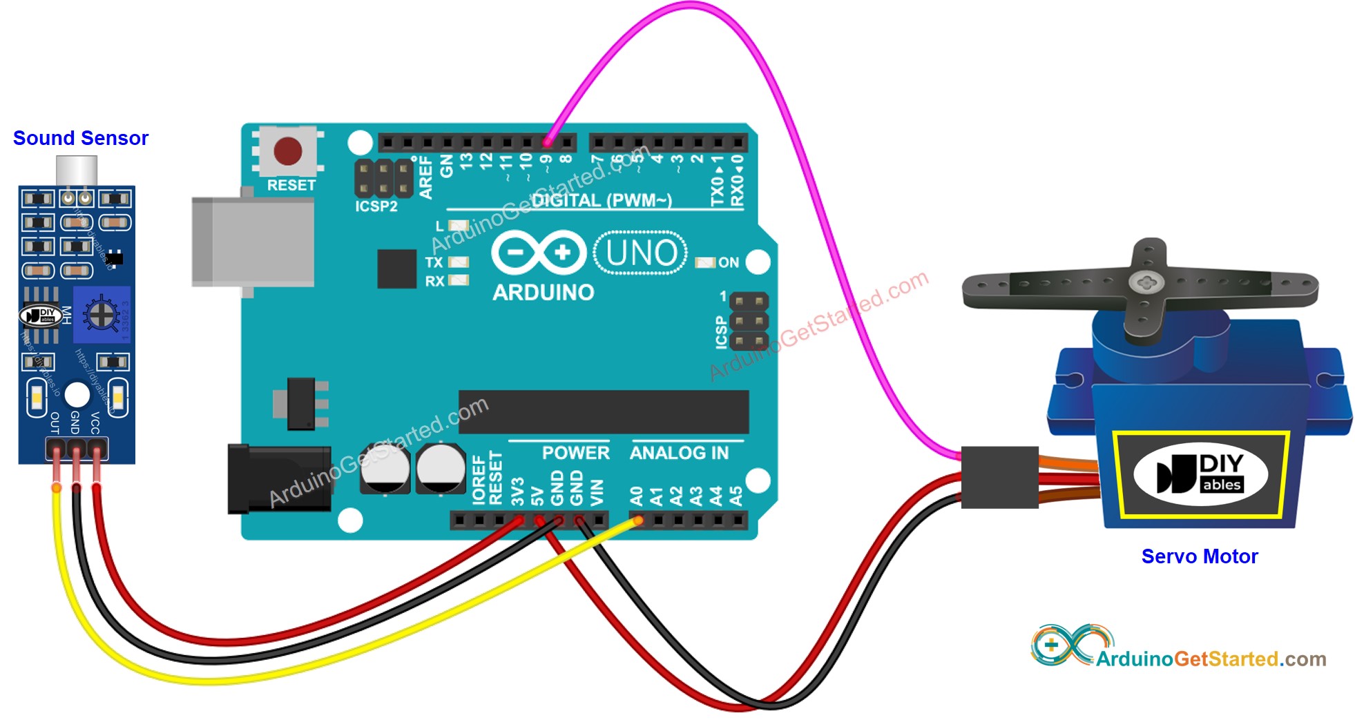
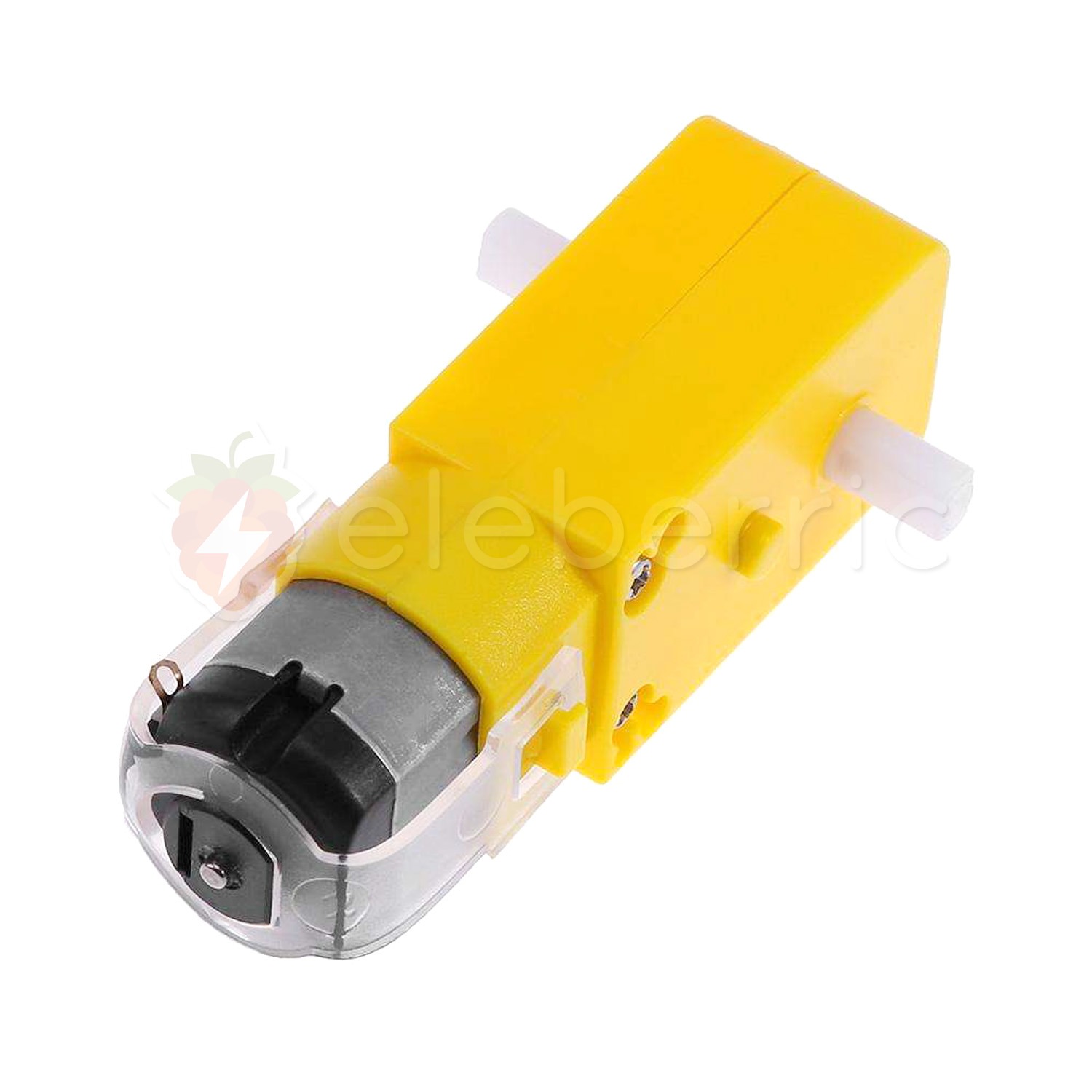
Motors & Motion
DC Motors: Spin when power is applied. Swap wires (+/-) to reverse direction.
The H-Bridge: A special chip that contains transistors to let us control motor direction and speed (via PWM) from code.
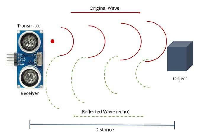
Application: Distance Sensors
Ultrasonic Sensor (HC-SR04): Works like a bat.
1. Trig pin sends a high frequency sound 'ping'.
2. Sound bounces off object and returns to Echo pin.
3. Distance = (Time x Speed of Sound) / 2
Thinking: Logic Statements
IF (Distance < 10) { Stop Motors; Turn LED ON; } ELSE { Drive Forward; Turn LED OFF; }
The 'IF' statement is the core of robotics. It connects the Sense (Distance) to the Act (Motors).
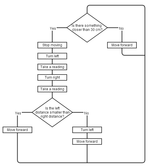
Visualizing Logic: The Flowchart
Always draw a flowchart BEFORE writing code.
Diamonds = Decisions (Yes/No).
Rectangles = Actions (Turn on LED, Run Motor).
Summary & Challenge
Recap:
1. Sensors (Inputs) can be Digital (Switch) or Analog (Light/Temp). 2. Actuators (Outputs) need drivers (Transistors) for high power. 3. Logic (IF/ELSE) connects them.
Design Challenge:
Design a 'Smart Fan' system. It should turn ON a fan (Motor) when the temperature (Thermistor) gets too hot, but ONLY if someone is in the room (Motion Sensor). Draw the flowchart.
- electronics
- sensors
- microcontroller
- arduino-basics
- robotics
- digital-analog
- stemeducation