
BBQ Grill Design: Engineering Stress & Thermal Analysis
Step-by-step stress analysis and design validation for a foldable BBQ grill, covering static loads, buckling, thermal expansion, and stability.
Foldable BBQ Grill: Engineering Stress Analysis
Design Validation, Static Loads & Thermal Effects | 300x230mm Platform
1. Design Parameters & Material Specs
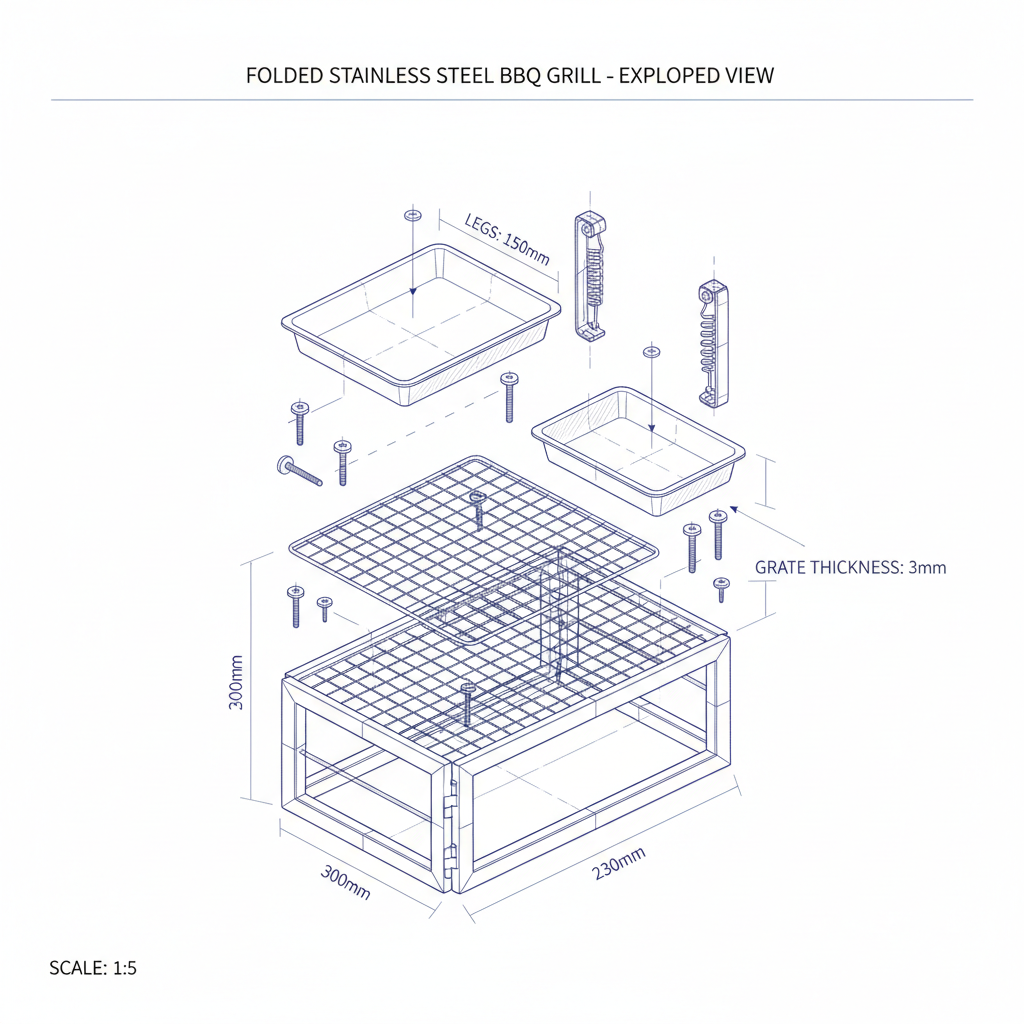
• Dimensions: 300mm (L) x 230mm (W) x 150mm (H)<br>• Mechanism: Hinged folding legs, removable grate.<br>• Material: AISI 304 Stainless Steel (Sheet & Rod).<br>• Sheet Thickness: 0.8mm (Body), 3.0mm (Grate Rods).<br>• Fasteners: 4mm SS Rivets.
2. Load Case Definition (Static)
<strong>Assumptions:</strong><br><br>1. Max Food Load: 5.0 kg (Dense meat packing)<br>2. Fuel Load: 2.0 kg (Coals/Briquettes)<br>3. Grate/Acc Weight: 1.0 kg<br>-----------------------------------<br><strong>Total Design Load (P_total):</strong><br>P = (5 + 2 + 1) * 9.81 m/s²<br>P ≈ 78.5 N -> <strong>Round to 80 N</strong><br><br><strong>Distribution:</strong><br>Distributed uniformly across 230mm span.
3. Grate Bending Stress Analysis
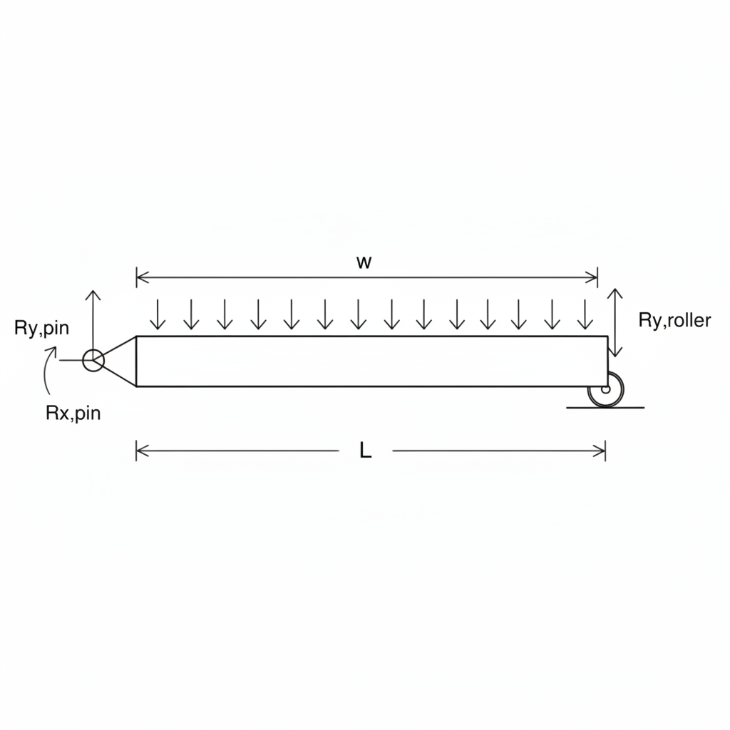
<strong>Model:</strong> Single rod simply supported beam.<br><strong>Load per rod (15 rods):</strong> 80N / 15 = 5.33 N<br><strong>Span (L):</strong> 230 mm<br><strong>Rod Dia (d):</strong> 3.0 mm<br><br><strong>Moment of Inertia (I):</strong><br>I = (π * d⁴) / 64 = (π * 3⁴) / 64 = <strong>3.976 mm⁴</strong><br><br><strong>Max Moment (M):</strong><br>M = (w * L) / 4 Assuming point load worst case center<br>M = (5.33 * 230) / 4 = <strong>306.4 N-mm</strong><br><br><strong>Bending Stress (σ):</strong><br>σ = (M * y) / I = (306.4 * 1.5) / 3.976<br>σ = <strong>115.6 MPa</strong>
<strong>Result Analysis:</strong><br>Yield Strength (Sy) = 215 MPa<br>Max Stress (σ) = 115.6 MPa<br><br><strong>Margin of Safety (MoS):</strong><br>MoS = (Sy / σ) - 1<br>MoS = (215 / 115.6) - 1 = <strong>0.86</strong><br><span style='color:green; font-weight:bold;'>PASS (Elastic Deformation Only)</span>
4. Leg Strut Buckling Calculation
FAILURE MODE: Euler Buckling of thin leg strut.<br><br><strong>Specs:</strong><br>Cross-section: 15mm x 0.8mm strip (bent)<br>Length (L effective): 160mm<br>Area Moment (I_min): Approx 6.4 mm⁴ (Weak axis)<br><br><strong>Critical Load (P_cr):</strong><br>P_cr = (π² * E * I) / (K * L)²<br>Assume K=1 (Pinned-Pinned)<br>P_cr = (π² * 193000 * 6.4) / (160)²<br><strong>P_cr = 476.2 N</strong> (Per Leg)
<strong>Applied Load:</strong><br>Total 80N shared by 4 legs = 20N / leg.<br><br><strong>Factor of Safety (FoS):</strong><br>FoS = P_cr / P_actual<br>FoS = 476.2 / 20 = <strong>23.8</strong><br><br><span style='color:green;'>CONCLUSION: No buckling risk for vertical loads.</span><br><span style='font-size:18px; color:#777;'>(Risk lies in lateral bending, not vertical buckling)</span>
5. Hinge Pivot Shear Stress
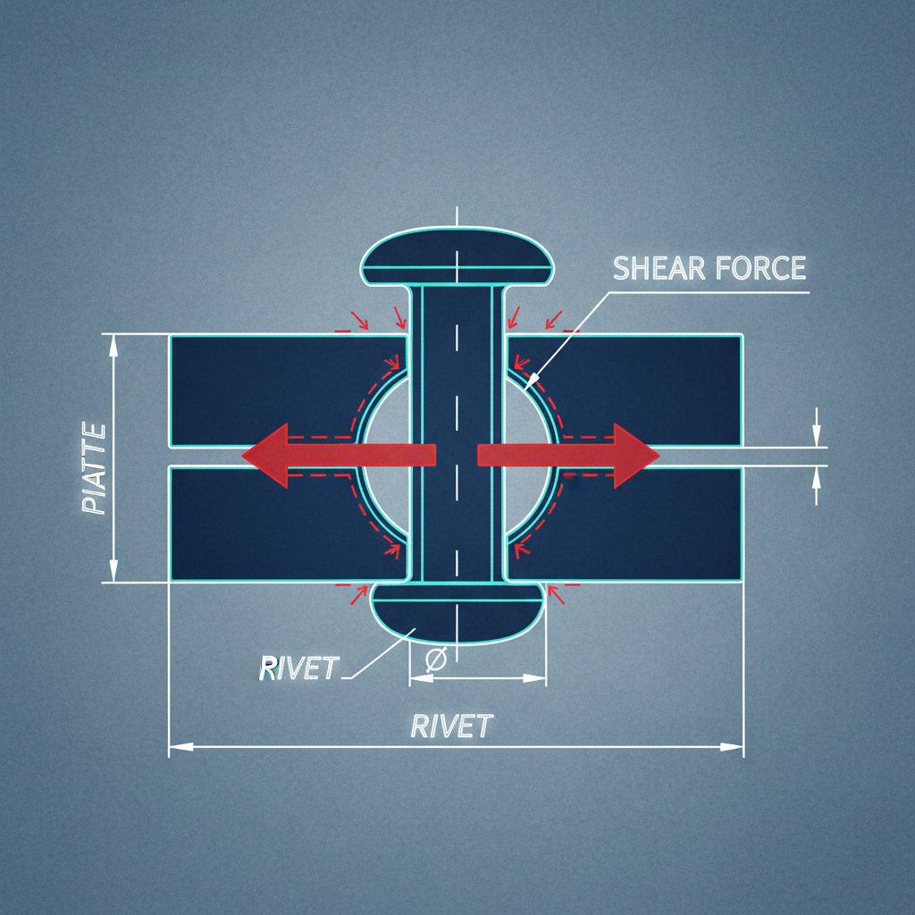
<strong>Element:</strong> 4mm SS Rivet at main pivot.<br><br><strong>Shear Area (A):</strong><br>A = π * r² = π * 2² = <strong>12.57 mm²</strong><br><br><strong>Shear Force (V):</strong><br>Assume dynamic drop scenario (3g impact).<br>Load = 20N (static per leg) * 3 = 60N.<br><br><strong>Shear Stress (τ):</strong><br>τ = V / A = 60 / 12.57 = <strong>4.77 MPa</strong>
<strong>Check:</strong><br>SS 304 Shear Yield ~ 0.5 * Tensile Yield<br>τ_yield ≈ 108 MPa.<br><br><strong>Result:</strong><br>4.77 MPa << 108 MPa.<br><strong>Rivet failure is negligible.</strong>
6. Thermal Expansion Calculation
<strong>Parameter:</strong> Linear expansion of main grate length.<br><br><strong>Data:</strong><br>L_original = 300 mm<br>T_ambient = 20°C<br>T_max = 450°C (Direct flame contact)<br>ΔT = 430 K<br>Coeff of Thermal Exp (α) = 17.3 × 10⁻⁶ /K<br><br><strong>Calculation:</strong><br>ΔL = α * L * ΔT<br>ΔL = 17.3e-6 * 300 * 430<br>ΔL = <strong>2.23 mm</strong>
<strong>Key Design Requirement:</strong><br>The frame slot must accommodate a 302.23mm grate.<br><br><strong>Design Action:</strong><br>Clearance gap set to <strong>3.0 mm</strong> total (1.5mm per side) to prevent thermal bowing/buckling of the frame.
7. Thermal Stress Analysis (Constrained)
WHAT IF: The 3mm gap is blocked by debris?<br><br><strong>Constrained Thermal Stress (σ_th):</strong><br>σ_th = E * α * ΔT<br>σ_th = 193000 * 17.3e-6 * 430<br>σ_th = <strong>1,435 MPa</strong><br><br><strong>IMPLICATION:</strong><br>1435 MPa >> 215 MPa (Yield).<br>If expansion is constrained, the unit WILL plastically deform (warp permanently) or buckle the frame.<br><strong>CRITICAL:</strong> Ensure non-jamming geometry.
8. User Load: Lateral Stability (Accidental Bump)
<strong>Scenario:</strong> 50N Horizontal force applied at top edge (User bumps grill).<br><br><strong>Moment Balance (Toppling):</strong><br>Pivot: Bottom of leg.<br>Height (h) = 150 mm.<br>Base Width (w) = 230 mm.<br>Weight (W) = 30N (approx structure + heavy coal).<br><br>Restoring Moment_R = W * (w/2) = 30 * 115 = 3450 N-mm.<br>Overturning Moment_O = F_lat * h = 50 * 150 = 7500 N-mm.<br><br><strong>Analysis:</strong><br>7500 > 3450.<br><strong>Grill will tip over at >23N lateral load.</strong>
<strong>Mitigation Strategy:</strong><br>To prevent tipping, legs must splay outward.<br>Design Change: Increase effective base width to > 350mm via angled legs (30° flare).
9. Manufacturing: Spot Weld Strength
<strong>Joint:</strong> Bracket to Main Body (Lap Joint).<br><strong>Weld nugget diameter:</strong> 4mm.<br>Area = 12.5 mm².<br><br><strong>Shear Strength of Weld:</strong><br>Approx 70% of Parent Metal UTS.<br>τ_weld = 0.7 * 505 MPa = 353 MPa.<br><br><strong>Max Capacity per Weld:</strong><br>F_max = τ_weld * Area = 353 * 12.5 = <strong>4,412 N</strong><br><br><strong>Applied Load:</strong><br>Max load seen at bracket ~ 80N.<br>FoS = 4412 / 80 = <strong>55</strong>.<br>Notes: Spot welds are non-critical for static load; failure mode is sheet tearing, not weld shear.
10. Summary: Safety Margins
<strong>Critical Action Items:</strong><br>1. Thermal clearance of 3mm is mandatory.<br>2. Lateral stability is the weakest point (Tip-over risk).<br>3. Material thickness (0.8mm) is sufficient for static loads.
- engineering-analysis
- mechanical-design
- stress-calculation
- bbq-grill-design
- structural-validation
- thermal-expansion
- cad-modeling