


Thermal Performance of a New Coiled Tube Heat Exchanger
Experimental study on figure-eight helical coil heat exchangers, exploring the impact of hot water inlet temperature and flow rate on heat transfer efficiency.
University of Karbala
Engineering College
Mechanical Engineering Department
Experimental Investigation of the Thermal Performance of a New Coiled Tube Heat Exchanger
A Project Submitted in Partial Fulfillment of Requirements for the Degree of Bachelor of Science in Mechanical Engineering
By
Faleh Mahdi Jasim | Arshad Yaseen Muhawes | Mohammad Jawad Kadhem
Supervised by
Assist. Prof. Abdalrazzaq Al-Shammari
May / 2026
Presentation Outline
Introduction & Background
Heat exchangers, problem statement, objectives
Literature Review
Flow techniques, types of HX, helical coil HX
Theoretical Calculations
Heat transfer rate, Nusselt number, Reynolds number, LMTD
Experimental Apparatus & Procedure
Test rig, thermocouples, flow meters, procedure
Results & Discussion
Nu number, heat transfer coefficient, heat transfer rate, Re
Conclusions & References
Key findings and references
Chapter 1
Introduction
1.1 What is a Heat Exchanger?
A heat exchanger is a device for transferring thermal energy from a high-temperature fluid to a low-temperature fluid. Widely used in refrigeration, air conditioning, chemical industry, power plants, and internal combustion engine cooling.
1.2 Shell & Helical Pipe Heat Exchanger (HTHE)
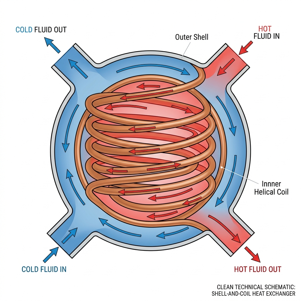
One of the simplest and most widely used types. Consists of two concentric pipes — one fluid flows inside the inner helical pipe, the other flows in the annular space (counterflow). Efficiently transfers heat without direct mixing.
1.3 Problem Statement
Experimental study of forced convection in a coiled circular pipe. Smooth twisted pipes significantly impact fluid flow, heat transfer improvement, and reduced pressure drop.
Chapter 1 — Continued
Objectives & Applications
Study Objectives
Applications
Thermal & Flow Performance
Investigate effects of helical shape using water as working fluid on thermal and flow fields and Performance Evaluation Criterion (PEC).
Friction Characteristics
Study effects of helical shape on friction in circular pipe side.
Cold Water Velocity Effects
Examine effects of cold water velocity range (0.293 – 0.646 m/s) on thermal and flow fields.
Condensers & Evaporators
Oil Radiators
Food Industry
Nuclear Reactors
Renewable Energy Systems
Air Conditioning & Thermal Storage
Industrial Boilers & Furnaces
Chemical Reactors & Piping Systems
Reynolds numbers range: 8,000 – 13,000 | Hot water temperature: 40–70°C | Cold water flow: 5–11 LPM
Chapter 2
Literature Review
Yuan et al. [11]
Experimental study of double shell-passes multi-layer helically coiled pipes heat exchanger (DSMHCTHE). Results showed:
Heat transfer rate increased by 5.1% to 12.9%
Overall heat transfer coefficient improved by 21.5% to 29.0%
Shell-side coefficient increased by 36.2% to 47.5%
Comprehensive performance improved by 12% vs. traditional MHCTHE
Inyang et al. [12]
Compared helical coil heat exchangers (HCHE) with straight pipe HX. HCHE demonstrated superior heat transfer performance due to secondary flow development inside the helical pipe. Heat transfer coefficient increased with curvature ratio.
LI Ya-xia et al. [13]
Spiral corrugation further enhances heat transfer of smooth helical pipe via additional swirling motion. Helical pipes with spiral corrugation show 50–80% increase in heat transfer; flow resistance 50–300% larger than smooth helical pipe.
Ahmed et al. [14]
Al₂O₃/water Nanofluid in helically coiled pipe studied numerically. Reduction in outer wall temperature at low Reynolds numbers (200, 600, 1500). Heat transfer increases compared to straight pipe due to secondary flow mixing.
Chapter 3
Theoretical Calculations
1. Heat Transfer Rate
2. Heat Transfer Coefficient
3. Nusselt Number
4. Reynolds Number
5. LMTD (Counter Flow)
Design Assumptions
Steady state condition
Counter-flow arrangement — no transverse mixing
No phase change inside heat exchanger
No internal heat generation
Temperature Distribution
(Counter-Flow Heat Exchanger)
Chapter 4
Experimental Apparatus & Test Rig
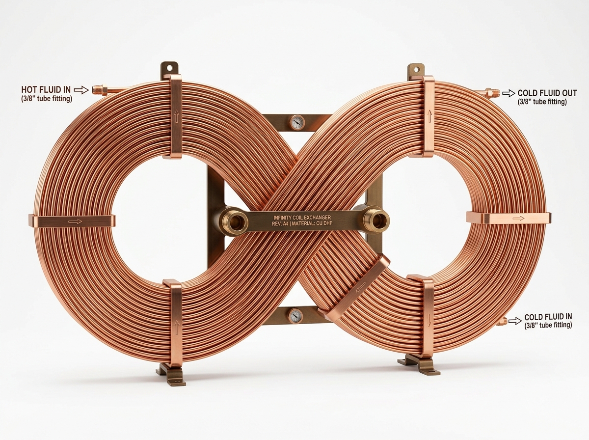
Novel ∞ Coil Design — 3,950 mm total length
Schematic Flow Diagram of Test Rig
Chapter 4 — Continued
Experimental Procedure
Fill heater with water; set hot water target temperature (40/50/60/70°C)
Open control valves; start cold water circulation pump
Set cold water flow rate to first value: 11 L/min
Start hot water circulation pump
Monitor thermocouple readings — wait 5–8 minutes for steady state
Record: hot flow rate, T<sub>hi</sub>, T<sub>ho</sub>, wall temperatures (T<sub>t1</sub>, T<sub>t2</sub>, T<sub>t3</sub>), T<sub>ci</sub>, T<sub>co</sub>, T<sub>s1</sub>
Change cold water flow rate to next value (9, 7, 5 L/min)
Repeat all steps for next hot water temperature setting
Test Matrix
Parameters Measured
Fluid inlet/outlet temperatures (shell & pipe)
Inner pipe wall temperatures
Volumetric flow rates (hot & cold)
Reynolds numbers: 8,000 – 13,000
CHAPTER 5
Results: Nusselt Number
Key Findings
Nu increases significantly with hot water inlet temperature
Higher Th,i → higher heat transfer coefficient → enhanced heat exchange
Maximum Nu ≈ 250 at Th,i = 70°C
Minimum Nu ≈ 55–70 at Th,i = 40°C
Nu increases with cold water velocity (higher Re)
The ∞-shaped helical coil promotes turbulence and secondary flow
Chapter 5 — Continued
Results: Heat Transfer Coefficient
Key Findings
<i>h</i> increases significantly with hot water inlet temperature
When T<sub>h,i</sub> increases from 40°C to 70°C: heat transfer coefficient increases by ~70%
At 70°C: <i>h</i> ≈ 12,000 W/m²K (maximum)
At 40°C: <i>h</i> ≈ 2,500 W/m²K (minimum)
Higher temperature difference → stronger convective currents → improved mixing → higher <i>h</i>
The ∞-shaped helical coil induces centrifugal secondary flow, significantly boosting <i>h</i> compared to straight pipes
70% improvement in heat transfer coefficient when T<sub>h,i</sub> increases from 40°C to 70°C
Chapter 5 — Continued
Results: Heat Transfer Rate & Reynolds Number
Heat transfer rate increases 10%–40% with rising hot water inlet temperature
From 40°C to 70°C: Q increases by 40%, 30%, and 9% respectively
Higher flow velocity increases Re → slightly higher Q
For liquids: higher temperature → lower viscosity → higher Re → more turbulent flow
Reynolds number range: 8,000 – 13,000 (fully turbulent regime)
“ The ∞ (figure-eight) coil design with passive heat transfer enhancement significantly outperforms traditional single-loop configurations ”
Chapter 5 — Conclusions
Conclusions & References
The novel ∞ (infinity/figure-eight) shaped helical coil significantly increases heat transfer surface area and induces secondary flow, enhancing overall thermal performance.
Nusselt number increases with increasing hot water inlet temperature: maximum Nu ≈ 250 at Th,i = 70°C.
Heat transfer coefficient increases by ~70% when inlet temperature rises from 40°C to 70°C (h reaches ~12,000 W/m²K).
Heat transfer rate increases by 10%–40% with rising temperature differential; cold water flow rate increase further boosts performance.
Reynolds numbers (8,000–13,000) confirm fully turbulent flow regime, favorable for heat transfer enhancement.
Higher hot water temperature leads to reduced viscosity, higher Re, and more turbulent flow, creating a self-reinforcing enhancement mechanism.
[11] Yuan et al. — Double shell-passes multi-layer helically coiled HX. Int. J. Heat Mass Transfer.
[12] Inyang et al. — Heat Transfer in Helical Coil HX. Univ. of Uyo, Nigeria.
[13] LI Ya-xia et al. — Helical Pipes with Spiral Corrugation.
[14] Ahmed & Hossain — Al₂O₃/Water Nanofluid in Helically Coiled Pipe.
Thank You for Your Attention
Questions are Welcome
University of Karbala | Engineering College | Mechanical Eng. Dept | May 2026
- heat-exchanger
- mechanical-engineering
- thermodynamics
- thermal-performance
- helical-coil
- fluid-dynamics
- energy-efficiency