
Mastering LoRaWAN: Architecture and Packet Structures
An in-depth guide to LoRaWAN architecture, PHY payload structures, OTAA join procedures, and application server integration for IoT deployments.
Mastering LoRaWAN
Architecture, Packet Structures, and Protocol Mechanisms
Why LoRaWAN?
LoRaWAN (Long Range Wide Area Network) is designed for low-power, wide-area IoT deployments. It bridges the gap between short-range protocols like Wi-Fi/BLE and expensive cellular networks. Key advantages include deep indoor penetration, unlicensed spectrum usage (ISM bands), and geolocation capabilities without GPS.
Range vs. Power Consumption Comparison
LoRaWAN offers a unique balance compared to Wi-Fi and Bluetooth, providing kilometers of range while maintaining minimal power consumption suitable for batteries lasting 5-10 years.
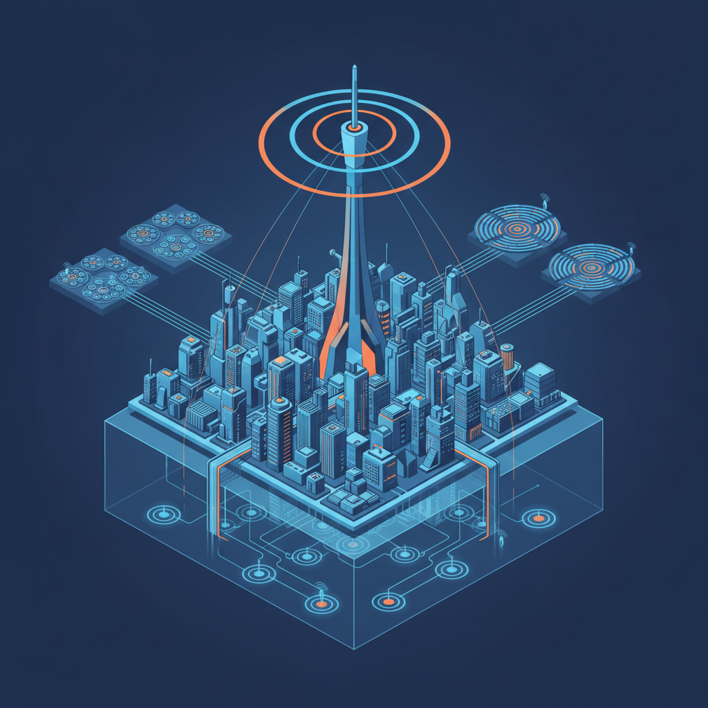
LoRaWAN Architecture Layers
End Devices: Sensors or actuators that transmit small packets of data wirelessly using LoRa modulation.
Gateways: Mere transparent bridges relaying RF packets between end-devices and the central Network Server via IP backhaul.
Network Server: The brain of the network. It de-duplicates packets, manages ADR (Adaptive Data Rate), and handles security (OTAA joining).
Application Server: Handles decrypting the application payload and processing the business logic.
Network Toplogy: Star-of-Stars
Devices broadcast to all hearable Gateways. No meshing.
LoRaWAN PHY Payload Structure
The PHYPayload is the top-level structure transmitted over the air. It encapsulates everything.
MHDR (MAC Header - 1 Byte): Specifies message type (Join Request, Data Up/Down) and LoRaWAN major version.
MACPayload (Variable): Contains the Frame Header (FHDR) and Port (FPort) plus the actual Frame Payload (FRMPayload). in Join requests, this contains Join EUI/Dev EUI.
MIC (Message Integrity Code - 4 Bytes): A cryptographic signature used to verify the packet's authenticity.
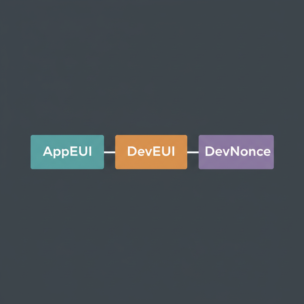
Join Request Packet Structure
Initiated by the End Device during Over-The-Air Activation (OTAA). It is not encrypted but is signed with a MIC.

Structure:
1. AppEUI (8 Bytes): Unique Application ID.
2. DevEUI (8 Bytes): Unique Device ID.
3. DevNonce (2 Bytes): Random/Counter value to prevent replay attacks.
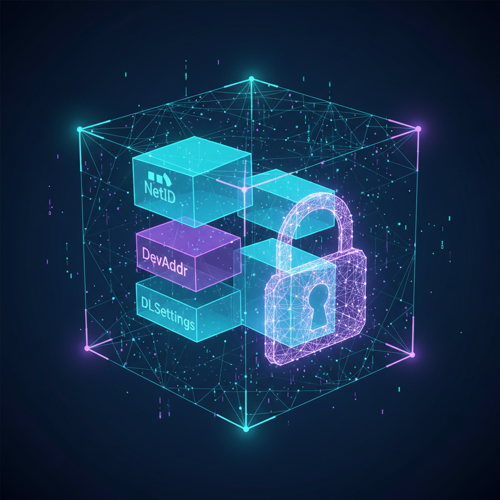
Join Accept Packet Structure
Sent by the Network Server if the device is permitted to join. The entire payload is encrypted with the AppKey.

Fields contain network parameters:
- AppNonce (3B): Random server value.
- NetID (3B): Network Identifier.
- DevAddr (4B): Assigned short address.
- DLSettings (1B): Downlink configuration.
- RxDelay (1B): Delay between TX and RX.
- CFList (16B): Optional channel frequency list.
Gateway Push/Pull Protocol (Semtech UDP)
The Gateway communicates with the Network Server over IP using a UDP-based protocol (typically on port 1700).
PUSH_DATA: Sent by Gateway to Server. Contains the JSON payload of the received RF packet + metadata (RSSI, SNR, timestamp).
PUSH_ACK: Acknowledgment from Server to Gateway confirming receipt of PUSH_DATA.
PULL_DATA: Sent periodically by Gateway to Server. It acts as a 'keep-alive' and opens the firewall port to receive downstream data (PULL_RESP) from the Server.
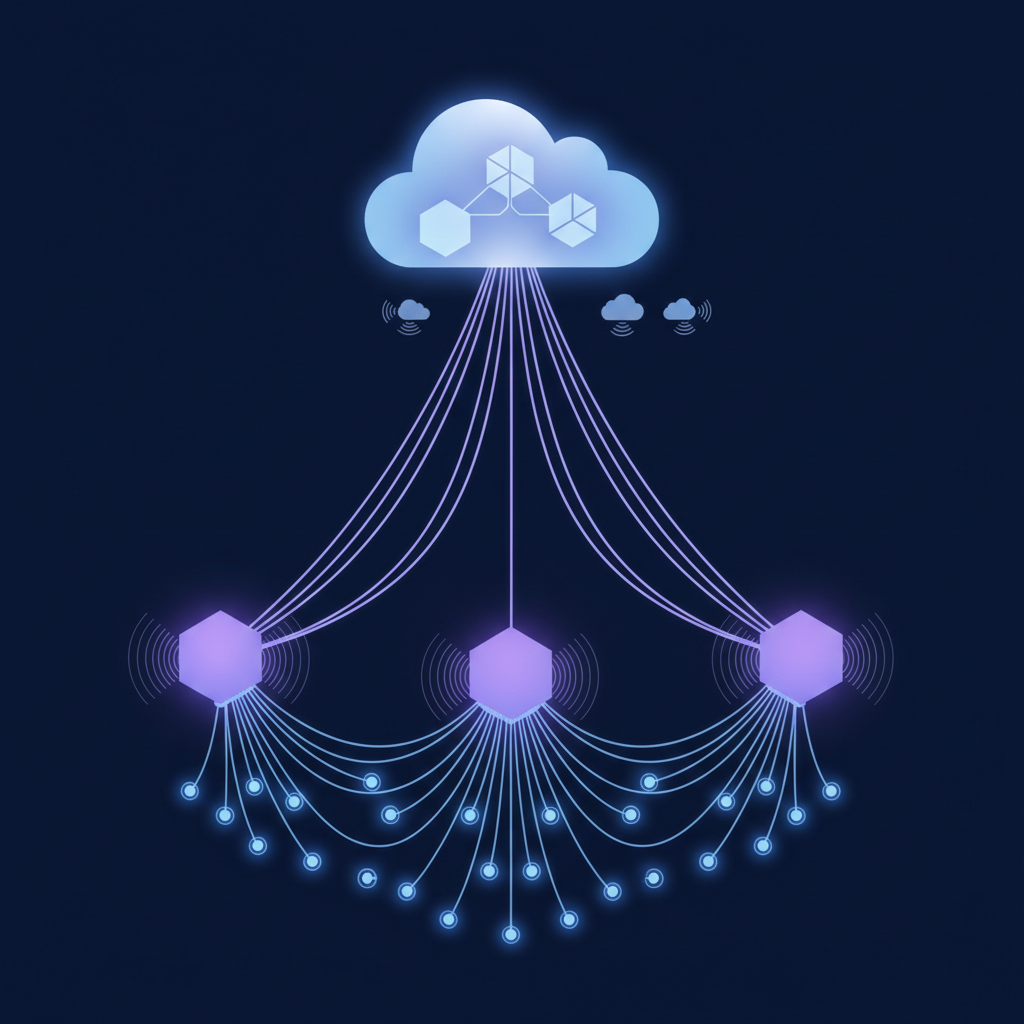
Application Layer Integration
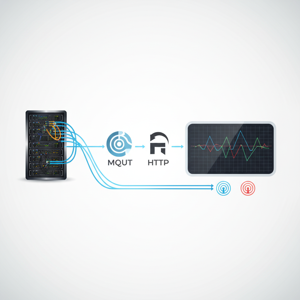
The Network Server forwards the application payload to the App Server. At this stage, LoRaWAN specifics are stripped away, and standards like MQTT or HTTP are used. 1. Payload Decoding: Raw bytes are converted to JSON objects (e.g., '0x0182' -> {'temp': 24.5}). 2. Integrations: Data is pushed via Webhooks or MQTT topics (e.g., application/1/device/abc/rx). 3. End User: Dashboards visualize the decoded data.
- lorawan
- iot
- network-architecture
- packet-structure
- otaa
- mqtt
- gateways
- lpwan