

Hydraulic Gear Transmission: Design and Working Principles
Explore the fundamentals of gear ratios, power transmission, and hydraulic actuation through a miniature model study using Pascal’s Law and DC motors.
MANGALORE INSTITUTE OF TECHNOLOGY & ENGINEERING
(A Unit of Rajalaxmi Education Trust®, Mangalore) Autonomous Institute affiliated to VTU, Belagavi, Approved by AICTE, New Delhi Accredited by NAAC with A+ Grade & ISO 9001:2015 Certified Institution
DEPARTMENT OF MECHANICAL ENGINEERING
Miniature Model Report on "Hydraulic Gear Transmission"
Mohammed Ebrahim Ravi kiran Sreerag KV
Mr. AVINASH HEGDE
2025-26
This is to certify that the Miniature Model entitled "Hydraulic Gear Transmission" was carried out by Mohammed Ebrahim, Ravi kiran, and Sreerag KV, students of the 1st Semester, and is accepted as the model work submitted in fulfilment of the requirement for the completion of the "Fundamentals of Mechanical Engineering" course (Code: 23ESCC113) during the academic year 2025-26.
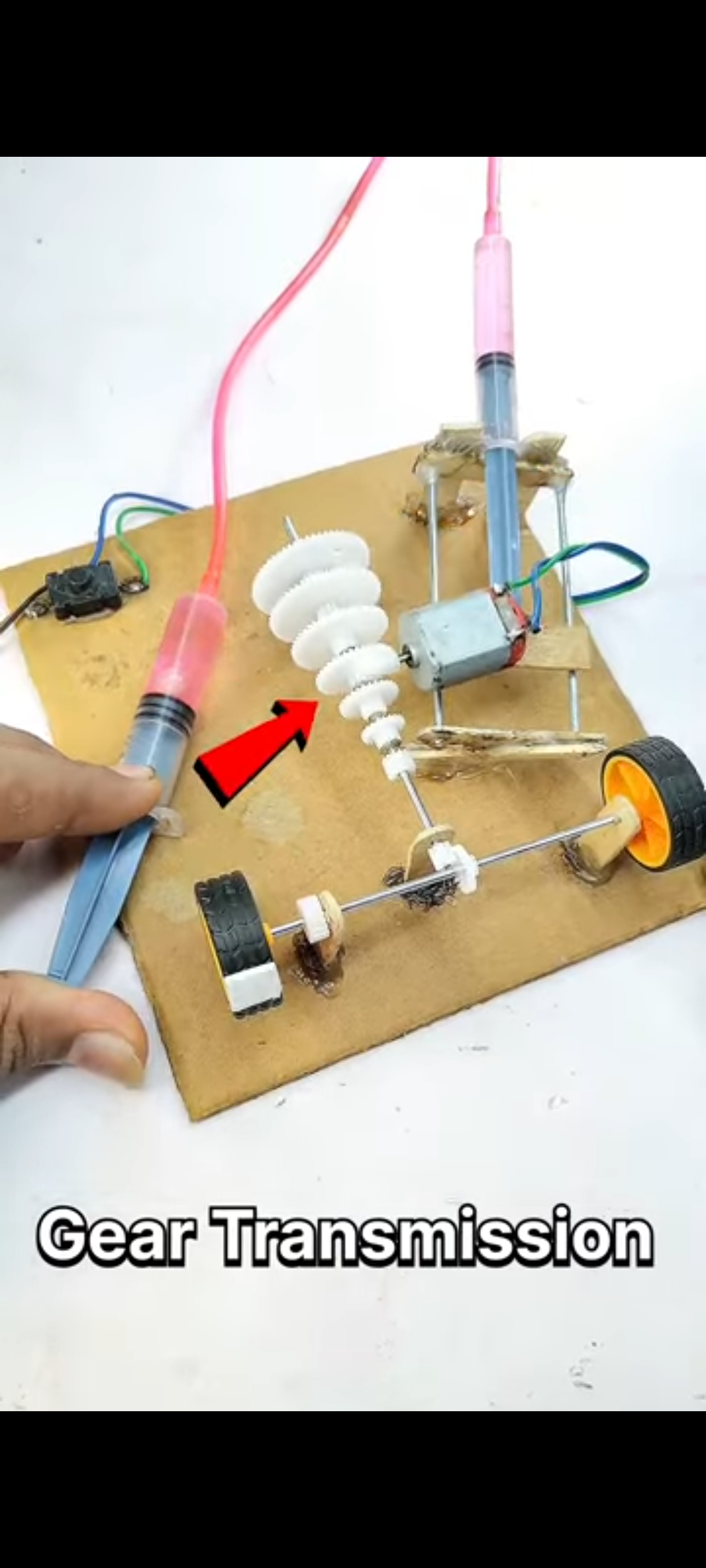
Fig. Miniature Model of Hydraulic Gear Transmission
INTRODUCTION
The Hydraulic Gear Transmission model is a mechanical device designed to demonstrate the fundamental principles of torque conversion, speed variation, and hydraulic actuation.<br><br>Unlike fixed-drive systems, this model showcases how different gear ratios can be utilized to alter the output speed and torque of a rotating shaft. Furthermore, it integrates a hydraulic shifting mechanism (using syringes) to simulate the gear-engagement process found in modern machinery.<br><br><b>Educational Focus:</b><br>- <b>Power Transmission:</b> Energy transfer from motor to driven shaft.<br>- <b>Gear Ratios:</b> Relationship between speed and torque.<br>- <b>Fluid Mechanics:</b> Pascal’s Law for actuation.
WORKING PRINCIPLE
<b>1. Gear Meshing / Transmission</b><br>The motor shaft connects to a driver gear which meshes with a driven gear (or cone stack). Changing engaged gears alters the ratio:<br>- <i>Small Driver → Large Driven:</i> Increases Torque, Decreases Speed.<br>- <i>Large Driver → Small Driven:</i> Decreases Torque, Increases Speed.
<b>2. Hydraulic Actuation</b><br>Uses two syringes connected by a fluid tube based on Pascal's Law.<br>- <b>Master Syringe:</b> Input force pushes fluid.<br>- <b>Slave Syringe:</b> Syringe extends to push the gear assembly laterally, simulating a clutch/shift mechanism.
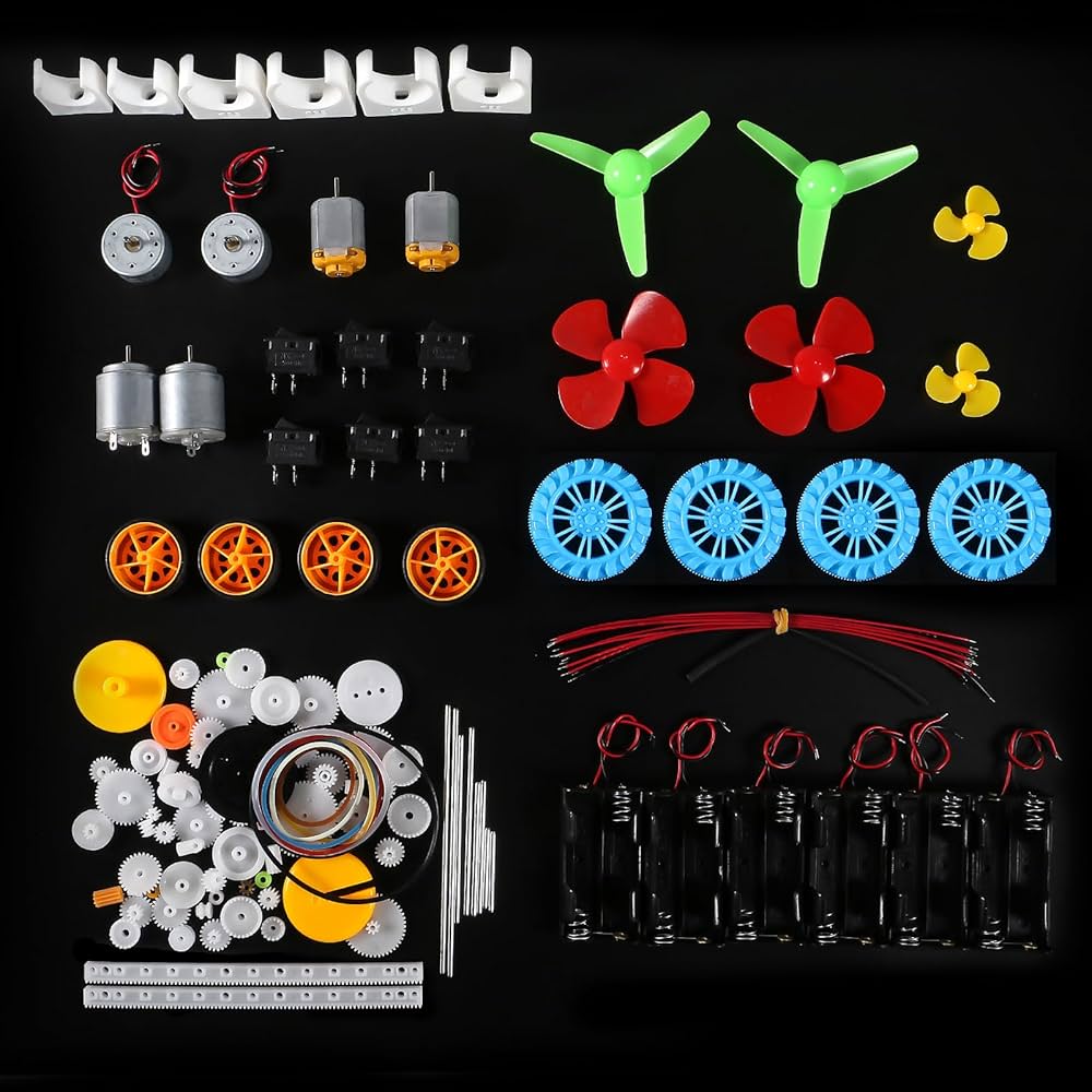
LIST OF COMPONENTS
<ul><li><b>DC Motor:</b> 12V High-Speed Motor</li><li><b>Gear Set:</b> Plastic Spur Gears / Cone Gears</li><li><b>Hydraulic System:</b> 10ml Syringes & Flexible Tubing</li><li><b>Shafts & Axles:</b> Steel or Plastic axles</li><li><b>Power Source:</b> 9V Battery</li><li><b>Base:</b> Rigid support platform (Cardboard/Wood)</li></ul>
DETAILS / SPECIFICATIONS
DC Motor
A permanent magnet DC motor responsible for generating the necessary RPM (Rotations Per Minute).
Gear Train
A set of meshing gears with varying teeth counts (e.g., 10T, 20T, 30T) to demonstrate step-up and step-down transmission.
Hydraulic Actuator
Utilizes Pascal’s Law. Pressure in master cylinder is transmitted to slave cylinder for mechanical movement.
Chassis
Stable frame holding motor and shafts in alignment to prevent gear slippage.
APPLICATIONS
<b>Automotive Industry:</b> The fundamental concept behind manual and automatic car gearboxes.
<b>Industrial Machinery:</b> Used in lathes, milling machines, and conveyor belts where variable speeds are required.
<b>Heavy Equipment:</b> Hydraulic shifting is widely used in excavators, cranes, and earth-movers.
<b>Robotics:</b> For joint actuation and torque management in robotic arms.
FUTURE SCOPE
<ul><li><b>Automation:</b> Integration of micro-servos and Arduino to shift gears automatically based on speed (Automatic Transmission).</li><li><b>CVT (Continuously Variable Transmission):</b> Replacing fixed gears with a belt-and-pulley system for seamless speed changes.</li><li><b>Sensors:</b> Adding RPM sensors to display real-time speed and gear ratio on an LCD screen.</li><li><b>Electrification:</b> Adapting the gearbox for high-efficiency Electric Vehicle (EV) powertrains.</li></ul>
REFERENCES
<ol><li>K.R. Gopalkrishna, <i>Elements of Mechanical Engineering</i>, Subhas Stores.</li><li>Basant Agrawal, <i>Basic Mechanical Engineering</i>, Wiley India.</li><li>Shigley's <i>Mechanical Engineering Design</i>, McGraw-Hill.</li><li>Standard engineering course materials for Code 23ESCC113.</li></ol>
- mechanical-engineering
- gear-transmission
- hydraulic-system
- pascal-law
- torque-conversion
- educational-model
- spur-gears