
Design and Analysis of a Gear Transmission System
Learn the principles of gear transmission, torque multiplication, and speed reduction through this mechanical engineering miniature model project report.
MANGALORE INSTITUTE OF TECHNOLOGY & ENGINEERING
Miniature Model Report on "Gear Transmission"
1. Mohammed Ebrahim<br>2. Ravi kiran<br>3. Sreerag KV
2025-26
CERTIFICATE
This is to certify that the Miniature Model entitled <strong>"Gear Transmission"</strong> was carried out by <strong>Mohammed Ebrahim, Ravi kiran, and Sreerag KV</strong>, students of the 1st Semester. It is accepted as the model work submitted in fulfilment of the requirement for the completion of the miniature Fundamentals of Mechanical Engineering course (23ESCC113) during the academic year 2025-2026.
<table style='width:100%; border-collapse:collapse; text-align:center; margin-top:20px;'><tr><th style='border:1px solid black; padding:10px;'>Particulars</th><th style='border:1px solid black; padding:10px;'>Max. Marks</th><th style='border:1px solid black; padding:10px;'>Obtained Marks</th></tr><tr><td style='border:1px solid black; padding:10px;'>Miniature Model</td><td style='border:1px solid black; padding:10px;'>10</td><td style='border:1px solid black; padding:10px;'></td></tr><tr><td style='border:1px solid black; padding:10px;'>Report & Presentation</td><td style='border:1px solid black; padding:10px;'>10</td><td style='border:1px solid black; padding:10px;'></td></tr><tr><td style='border:1px solid black; padding:10px; font-weight:bold;'>Total</td><td style='border:1px solid black; padding:10px; font-weight:bold;'>20</td><td style='border:1px solid black; padding:10px;'></td></tr></table>
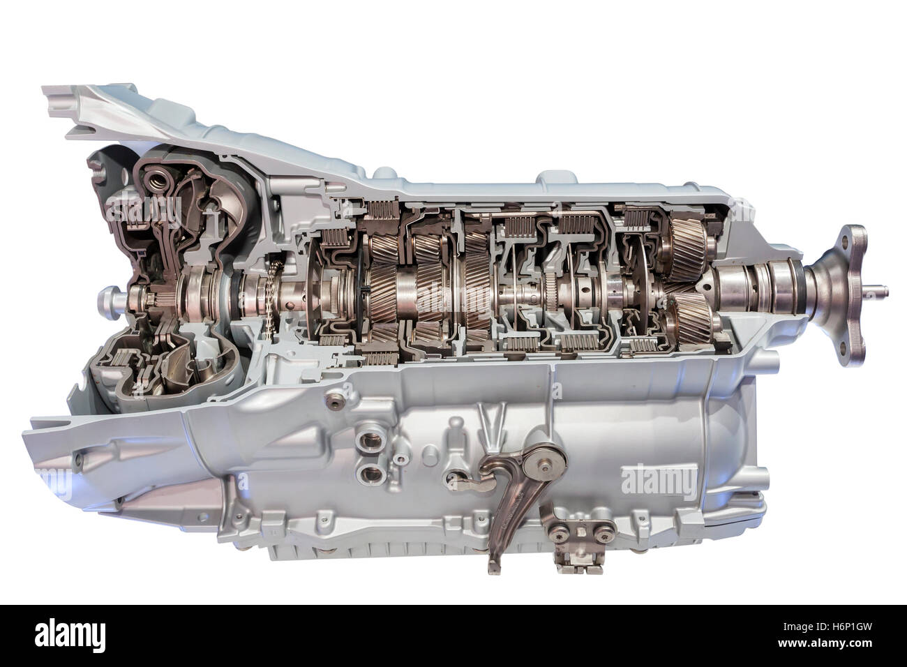
Fig. Miniature Model of Gear Transmission System
INTRODUCTION
The Gear Transmission Model is a compact mechanical setup designed to demonstrate the fundamental principles of torque multiplication and speed reduction. A compound gear train consists of multiple gears mounted on shafts to achieve higher gear ratios over short distances.<br><br>In mechanical engineering, this project serves as a practical demonstration of how rotational motion can be transferred and modified. It addresses the core concept of power transmission found in automobiles, industrial machinery, and robotics.
WORKING PRINCIPLE
• <b>Power Source:</b> A high-torque DC motor serves as the primary driver, converting electrical energy into rotational mechanical energy.
• <b>Transmission:</b> The motor shaft drives a smaller input gear (pinion). This gear meshes with a larger compound gear.
• <b>Motion Transfer:</b> According to the gear ratio principle, speed is reduced while torque is increased. The rotational force is eventually transferred to the output shaft.
• <b>Result:</b> The final output wheel rotates at a lower RPM but with sufficient torque to drive the load, demonstrating mechanical advantage.
LIST OF COMPONENTS USED
● 12V DC Motor<br><br>● Plastic Compound Gears<br><br>● Spur Gears (Pinions)<br><br>● Metal Shafts & Axles<br><br>● 9V Battery & Holder<br><br>● Connecting Wires & Switch<br><br>● Cardboard Base
Fig. Components
DETAILS / SPECIFICATIONS
<b>DC Motor:</b> High-torque 12V motor responsible for generating the necessary rotational speed for the input shaft.
<b>Gear Arrangement:</b> Uses a Simple Spur Gear Pair and Compound Gears to demonstrate variable gear ratios. Made of durable engineering plastic.
<b>Shaft & Axle:</b> Mild steel rods used to support the rotating elements. Aligned parallel to ensure proper tooth meshing.
<b>Base:</b> A rigid cardboard/plywood chassis that supports the motor and maintains the center distance between gears.
APPLICATIONS
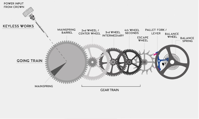
• <b>Automobile Gearboxes:</b> Used to change speed and torque according to road conditions.<br><br>• <b>Lathe Machines:</b> Gear trains in the headstock allow for different spindle speeds for machining different metals.<br><br>• <b>Clocks & Watches:</b> Precise compound gear trains facilitate timekeeping by reducing speed from the power spring.<br><br>• <b>Robotics:</b> Servo motors use internal gear trains to multiply torque for lifting heavy arms.
FUTURE SCOPE
<b>Automation:</b> Integration of stepper motors and microcontrollers to create a digital gearbox with programmable ratios.
<b>Material Upgrade:</b> Replacing plastic gears with 3D-printed Nylon or machined brass to handle higher loads and reduce wear.
<b>Efficiency Analysis:</b> Adding tachometers to measure input vs output RPM in real-time for lab efficiency experiments.
REFERENCE
1. K.R. Gopalkrishna, <i>Elements of Mechanical Engineering</i>, Subhas Stores.<br><br>2. R.S. Khurmi, <i>Theory of Machines</i>, S. Chand Publishing.<br><br>3. Shigley's <i>Mechanical Engineering Design</i>, McGraw-Hill.<br><br>4. Standard Engineering Lab Manuals and Datasheets.
THANK YOU
- gear-transmission
- mechanical-engineering
- torque-multiplication
- compound-gear-train
- spur-gears
- dc-motor
- engineering-project